Cable test bus and switch matrix circuit

A cable testing and switching matrix technology, applied in the direction of measuring resistance/reactance/impedance, measuring electricity, measuring devices, etc., can solve the problems of reducing test speed, large calibration workload, and long calibration time.

Inactive Publication Date: 2009-02-25
电信科学技术第五研究所有限公司
View PDF0 Cites 12 Cited by
  • Summary
  • Abstract
  • Description
  • Claims
  • Application Information

AI Technical Summary

Problems solved by technology

[0005] From attached figure 1 It can be seen from the figure that each test includes two different variables and different paths. Since the performance of each variable can not be consistent, it is necessary to perform a through calibration every time through different variables. 1 The attenuation of the normally open contact and the normally closed contact of the switch is different (see attached figure 2 ) causes the insertion attenuation of each path to be different, so a through calibration is required each time through a different path. The larger the number of line pairs, the more calibration times, the more time-consuming the calibration, and the lower test speed; as the number of tested line pairs increases, more switches are required, and the probability of failure in the circuit control part is greater

Method used


Image

  • Cable test bus and switch matrix circuit
  • Cable test bus and switch matrix circuit
  • Cable test bus and switch matrix circuit

Examples


Embodiment Construction

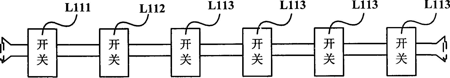
[0020] image 3 It is a schematic diagram of an embodiment of the first aspect of the present invention. Such as image 3 As shown, the CTB is composed of switches L111, L112, L113 with double-pole-double-throw function and differential line pairs. The moving contacts and normally closed contacts of the switches are connected to the differential line pairs (not shown in the figure).

[0021] image 3 The matching resistor indicated by the dotted line is used for CTB no-load matching, and the CTB is disconnected when it is used for testing.

[0022] The normally open contact of the switch is connected to the target (including the normally open contact of the switch on the other cable test bus and the cable under test), so the target is normally isolated from the CTB, providing the necessary conditions for the impedance matching of the CTB;

[0023] The switch has a DPDT function. A switch on the CTB receives a control signal to act, its normally open contact is closed, and t...


PUM


Abstract

The invention relates to a cable testing bus and a switching matrix circuit. The cable testing bus consists of a differential line pair and a double-pole-double-throw switch; the moving contact and the normally closed contact of the switch are connected on the differential line pair; the switching matrix circuit takes the cable testing bus as a main signal path, and comprises two transformers and four cable testing buses; and the coaxial end of the transformer is connected with the port of a testing apparatus, and the symmetrical end of the transformer is connected with the cable testing bus. The switching matrix circuit is characterized by cutting material cost, minimizing odds of testing equipment failure and reducing workload of nonstop calibration. The cable testing bus has the advantages that normal isolation from objective can be realized and the length of the cable testing bus can be controlled on the spot. Furthermore, the cable testing bus has sufficient bandwidth and constant characteristic resistance, and keeps working in matching condition, thereby ensuring measurement accuracy.

Description

technical field [0001] The invention relates to a measurement system circuit and its signal main channel, in particular to a cable test bus and a switch matrix circuit capable of reducing the number of equipment, accelerating the calibration speed and reducing equipment failure. Background technique [0002] A network analyzer is used as a measurement tool in a symmetrical cable (or other balanced component) test system. The network analyzer is a coaxial port. When testing a balanced object, a variable transformer needs to be used to complete the unbalanced / balanced conversion, and a switch circuit is used to complete the test target. convert. At present, the switch circuits used at home and abroad are all "single-pole, multiple-throw (SPNT)" coaxial switch circuits, and their structure is star-shaped. Since the "single-pole, double-throw" switch is generally used, only The SPNT can be formed by cascading switches. The "SPNT" type coaxial switch circuit first makes a coaxia...

Claims


Application Information

Patent Timeline
Patent Type & Authority Applications(China)
IPC IPC(8): G01R27/28G01R27/32G01R31/00
Inventor 才荫候谢云安
Owner 电信科学技术第五研究所有限公司
Why Eureka
Try Eureka