Device for the combustion of organic substances

一种有机物、设备的技术,应用在用于燃烧有机物的设备领域,能够解决废气余热未被利用等问题,达到穿流率改善的效果

Inactive Publication Date: 2009-03-11
沃尔特·弗莱勒
View PDF1 Cites 0 Cited by
  • Summary
  • Abstract
  • Description
  • Claims
  • Application Information

AI Technical Summary

Problems solved by technology

Although these measures give an advantageous preheating of the combustion air, the remaining waste heat of the exhaust gases is not used
This is also difficult because the combustion chamber is separated from the casing of the storage container used as a liquid heat carrier by means of thermal insulation, so that the exhaust gases have to be exported through the bottom of this combustion chamber

Method used


Image

  • Device for the combustion of organic substances
  • Device for the combustion of organic substances

Examples


Embodiment Construction

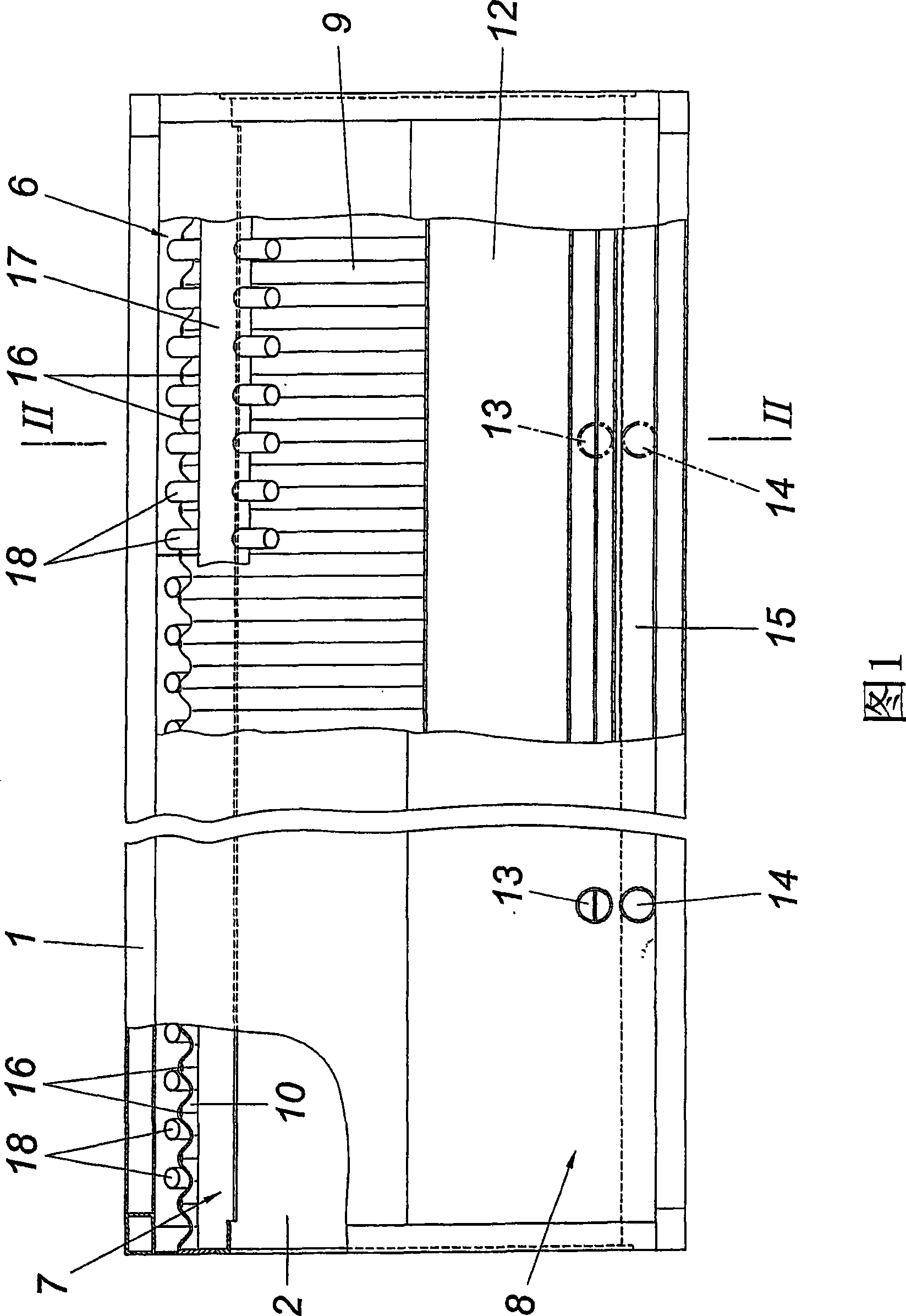
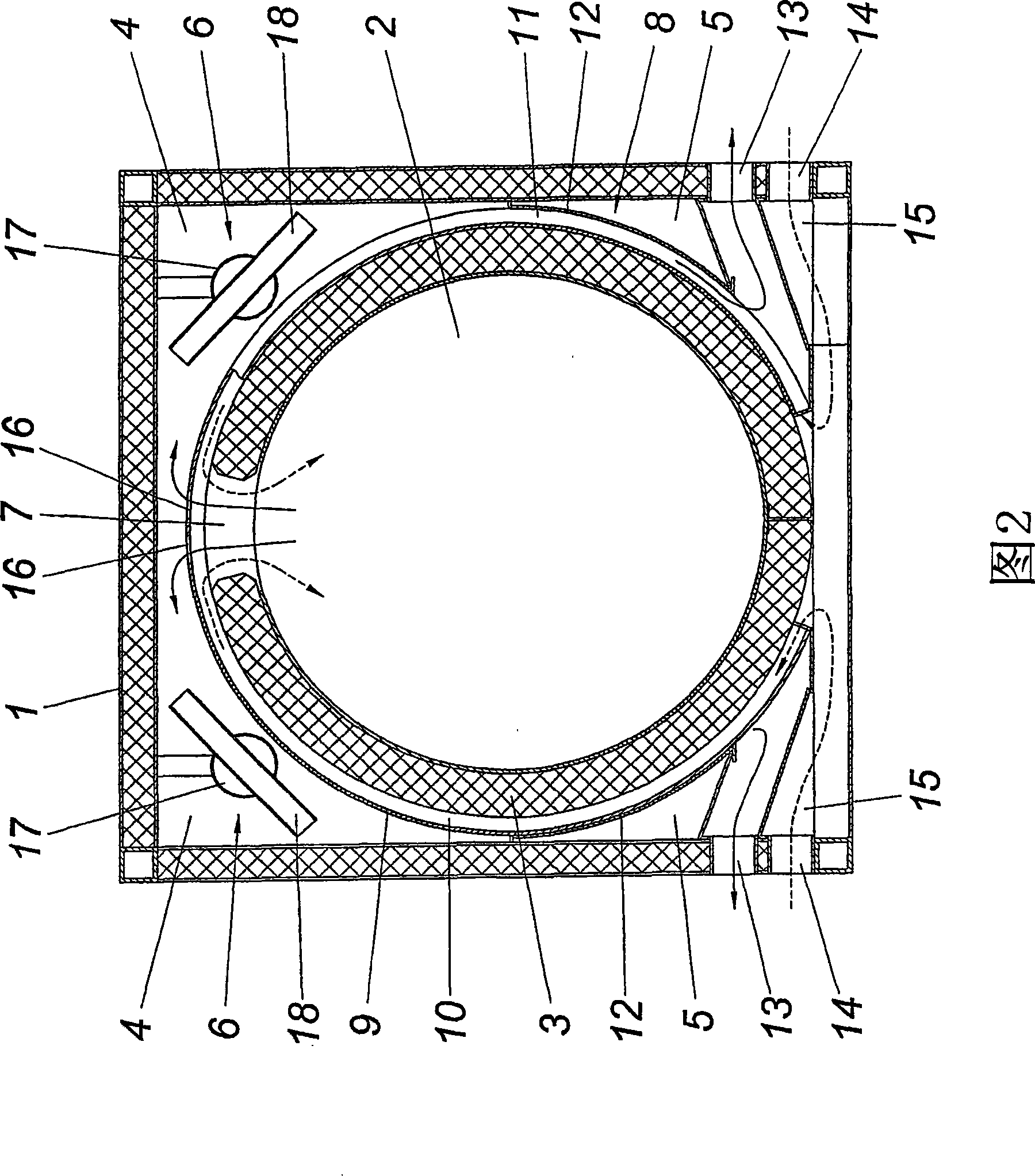
[0011] The device for burning organic matter, especially waste, has a prismatic housing 1 with a substantially cylindrical combustion chamber 2 with a square cross-section and a combustion chamber with a transverse axis. The combustion chamber is provided with thermal insulation means 3 shielding the combustion chamber with respect to the casing 1 . According to the arrangement of the substantially cylindrical combustion chamber 2 in the prismatic housing 1 with a square cross section, wedge-shaped cavities 4, 5 are obtained in the corner regions of the housing 1 between the combustion chamber 2 and the housing 1, in which The wedge-shaped cavity 4 on both sides of the upper part of the combustion chamber 3 accommodates a heat exchanger 6 for the heat carrier running parallel to the combustion chamber 2 .

[0012] The hot exhaust gases exit the combustion chamber 2 through exhaust gas outlet openings 7 arranged in the top region of the combustion chamber 2 and extend substanti...


PUM


Abstract

Described is a device for the combustion of organic substances, having a combustion chamber (2) which is provided in a housing (1) and is thermally insulated with respect to the housing (1), and having a countercurrent heat exchanger (8) which preheats the combustion air with the aid of the hot exhaust gases from the combustion chamber (2), which countercurrent heat exchanger (8) forms a flow duct (10), which is formed between the combustion chamber (2) and a heat exchanger wall (9) which surrounds the combustion chamber (2), for the combustion air, and a flow duct (11) for the hot exhaust gases on that side of the heat exchanger wall (9) which faces away from the combustion chamber (2). In order to create advantageous construction conditions, it is proposed that the heat exchanger wall (9) of the countercurrent heat exchanger (8) is provided on the outside of the thermal insulation (3) of the combustion chamber (2) which has an upper exhaust gas outlet (7) which opens out into the housing (1), that heat exchangers (6), which run parallel to the combustion chamber (2) and serve for the heating of a heat exchanger with the perceptible waste heat of the hot exhaust gases, are provided in the upper interstices (4) which are formed at both sides of the combustion chamber (2) between the combustion chamber (2) and the substantially prismatic housing (1), and that the flow duct (11), which receives the exhaust gases, of the countercurrent heat exchanger (8) for the combustion air proceeds from the two interstices (4), while the heat exchanger wall (9) extends with the flow duct (10) for the combustion air into the interstices (4).

Description

technical field [0001] The invention relates to a plant for the combustion of organic substances, which has a combustion chamber arranged in a casing, thermally insulated relative to the casing, and a combustion chamber with a preheating of the combustion air by means of hot exhaust gases from the combustion chamber A convective heat exchanger consisting of flow ducts for the combustion air formed between the combustion chamber and the heat exchanger wall surrounding the combustion chamber, and at the part of the heat exchanger wall facing away from the combustion chamber Flow ducts for hot exhaust air on one side. Background technique [0002] In order to burn organic matter, especially rubbish, it is known (US 5 315 938 A) that the combustion chamber, which is arranged in the shell, horizontally, and can be loaded in the axial direction, is provided with a thermal insulation device with respect to the shell containing the liquid heat carrier , in order to ensure favorable...

Claims


Application Information

Patent Timeline
Patent Type & Authority Applications(China)
IPC IPC(8): F23B80/04F23L15/00
CPCF23B80/04F23L15/00Y02E20/34
Inventor 沃尔特·弗莱勒
Owner 沃尔特·弗莱勒
Why Eureka
Try Eureka