
Silicone oil fan clutch
A clutch and silicone oil technology, which is applied in the field of silicone oil fan clutches, can solve the problems of limited thermal deformation of temperature sensing parts, limited working temperature range, and low control accuracy, and achieve a compact, reasonable and practical overall structure, wide temperature control range, and control high precision effect
- Summary
- Abstract
- Description
- Claims
- Application Information
AI Technical Summary
Problems solved by technology
Method used
Image

Examples
Embodiment
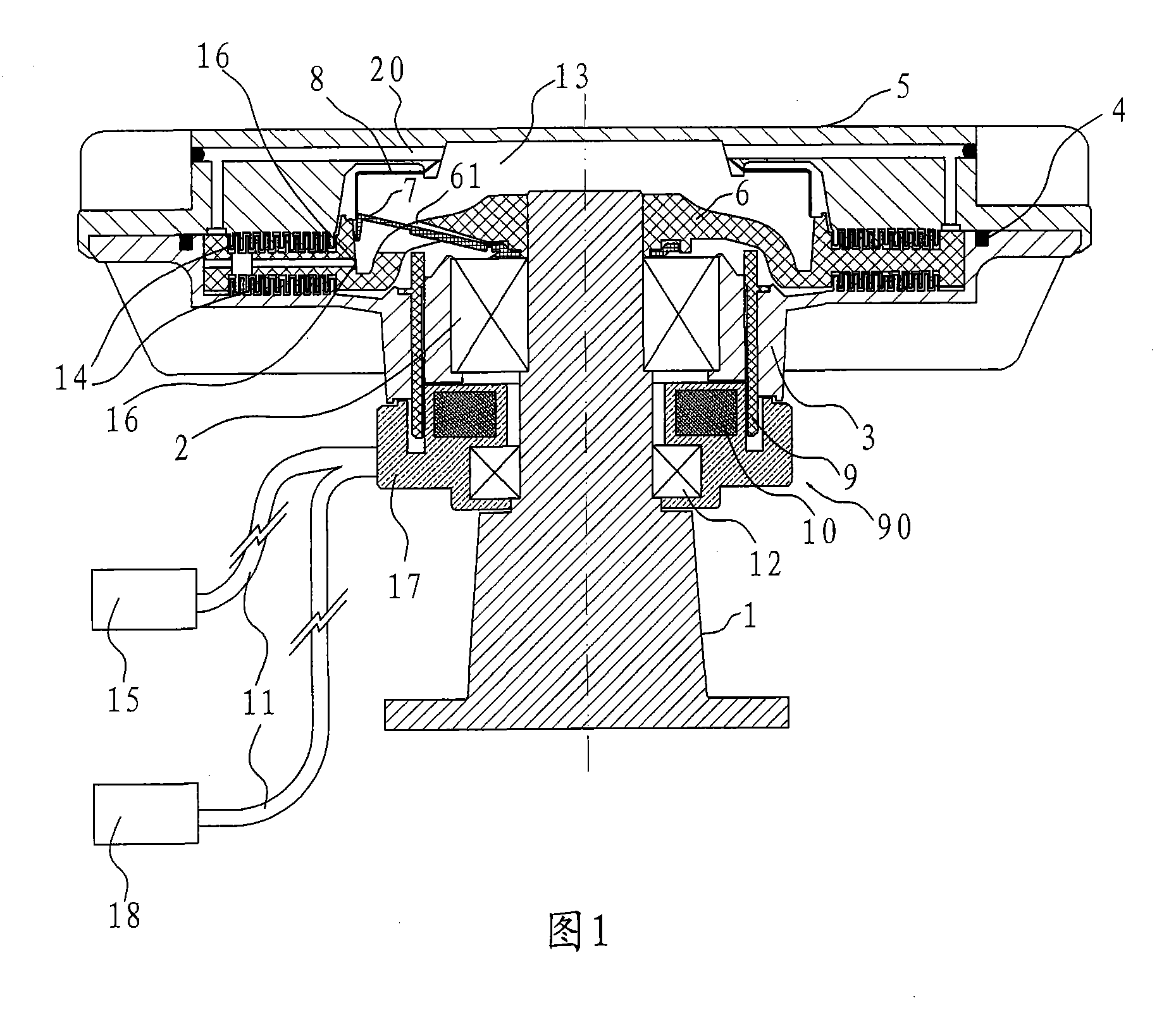
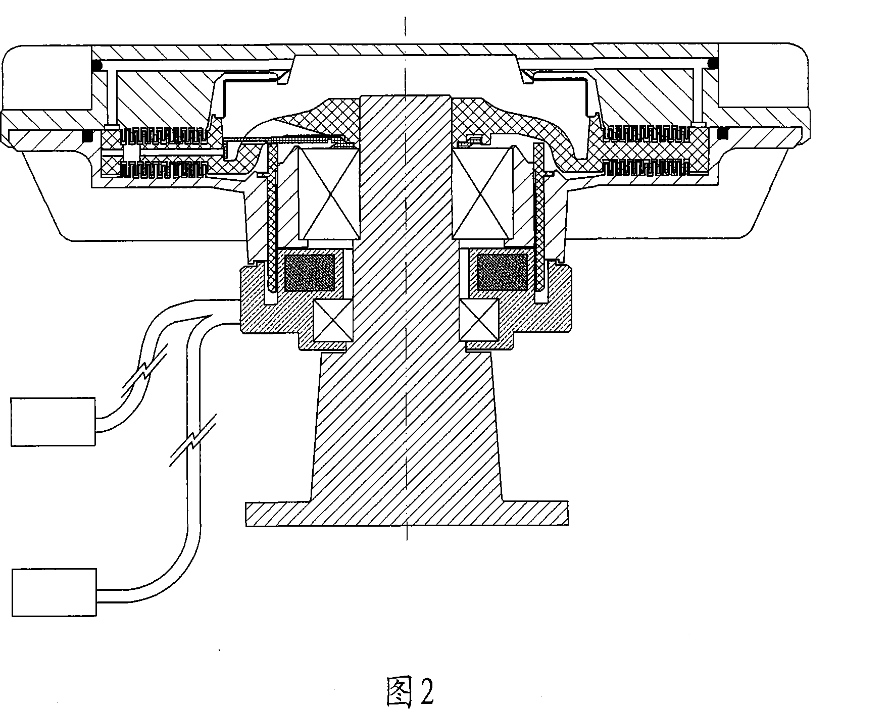
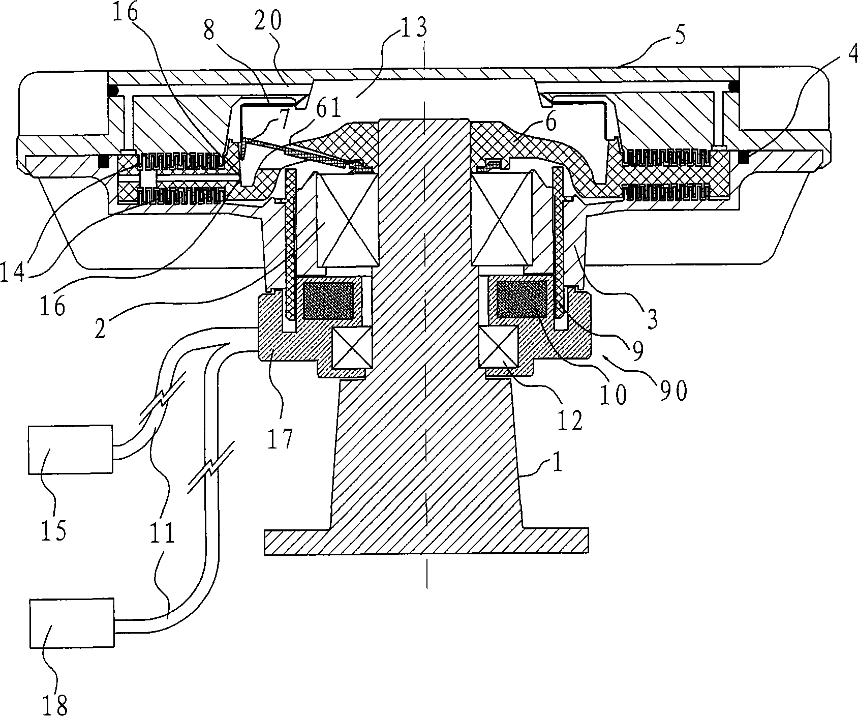
[0021] Example: Reference figure 1 with figure 2 shown.
[0022] The fan silicone oil clutch in this embodiment includes a driving shaft 1, a housing bearing 2, a housing 3, a front cover 5, a driving plate 6, a valve plate 7, an oil storage cover 8, an electromagnet 90 and an electromagnet bearing 12 . The housing 3 is inserted on the driving shaft 1 through a housing bearing 2 .
[0023] The drive shaft 1 is fixed in the middle of the housing 3 through the housing bearing 2, and the sealing ring 4 is fixedly connected between the front cover 5 and the housing 3; Engagement cavity 14; valve plate 7 has elasticity, one end of valve plate 7 is inlaid on active plate 6, and the other end is a free end that can open and close oil storage control hole 16. The active plate 6 is provided with a limiting hole 61 for limiting the valve plate 7 .
[0024] The oil storage cover 8 is fixedly connected with the active plate 6 to form an oil storage chamber 13, and there is silicone ...
PUM
 Abstract
Description
Claims
Application Information