Labor-saving transmission mechanism of bike

A transmission device and bicycle technology, which is applied in the field of vehicles, can solve the problems of short arm length, less labor saving, and difficulty in synchronous circular motion of the transmission rod.

Inactive Publication Date: 2009-07-15
韩东平
View PDF1 Cites 3 Cited by
  • Summary
  • Abstract
  • Description
  • Claims
  • Application Information

AI Technical Summary

Problems solved by technology

[0002] Due to the limitation of the pedaling position of the existing ordinary bicycles, the length of the single-arm lever used to connect with the pedals on the chain plate is relatively short, which is not very labor-saving.
A Chinese Utility Model Patent No. 200620158888.2 filed by the applicant of the present invention on November 9, 2006 discloses a "bicycle labor-saving transmission part". The bicycle moves forward: the first connection point and the second connection point of the transmission rod are respectively connected to the two "Z"-shaped connecting rods in rotation, and the third connection point is connected to the pedal or the handle device. The force makes the three connection points of the transmission rod move synchronously in a circular motion, so that the bicycle moves forward. However, it is found through experiments that: when the force is applied downward to th

Method used


Image

  • Labor-saving transmission mechanism of bike
  • Labor-saving transmission mechanism of bike
  • Labor-saving transmission mechanism of bike

Examples


Embodiment 1

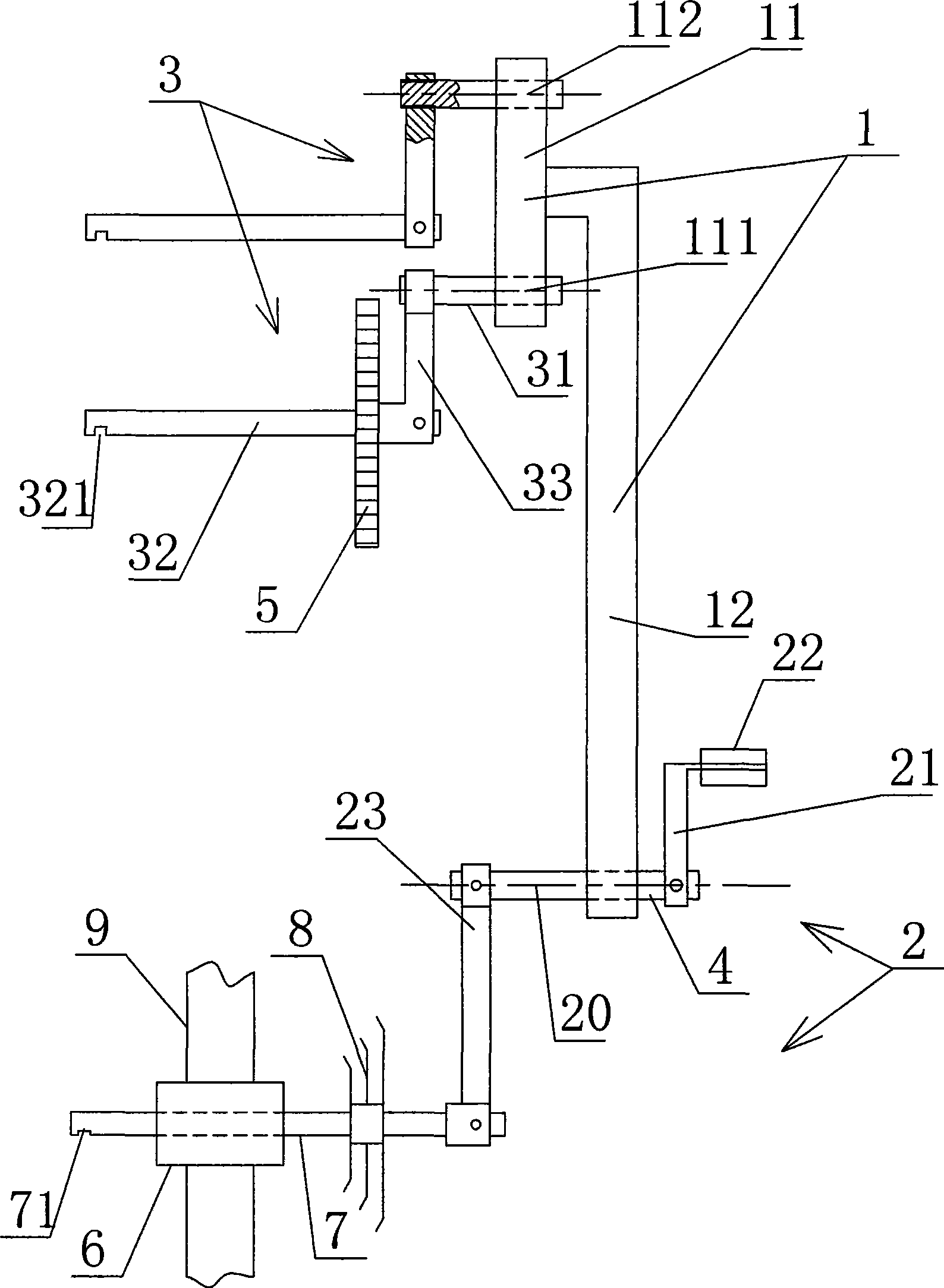
[0014] Such as figure 1 As shown, Embodiment 1 of the bicycle labor-saving transmission device of the present invention includes a transmission member 1, a pedal or handle device 2 connected to one end of the transmission member 1, a pair of "Z" shaped connecting rods 3 connected to the other end of the transmission member 1, and a pedal Or the connecting action centerline 20 of the handle device 2 connected to the transmission part 1 and the connection action centerlines 111, 112 of the two "Z" shaped connecting rods 3 connected to the transmission part are parallel to each other; each "Z" shaped connecting rod 3 is Comprising a pair of cross bars 31, 32 parallel to each other and a vertical bar 33 fixed between the two cross bars, wherein the second cross bar 32 is used to be rotatably connected with the bicycle frame (the second cross bar 32 can be set as Shaft rod, the shaft sleeve that is connected with the shaft rod is placed outside the shaft rod, so that the shaft slee...

Embodiment 2

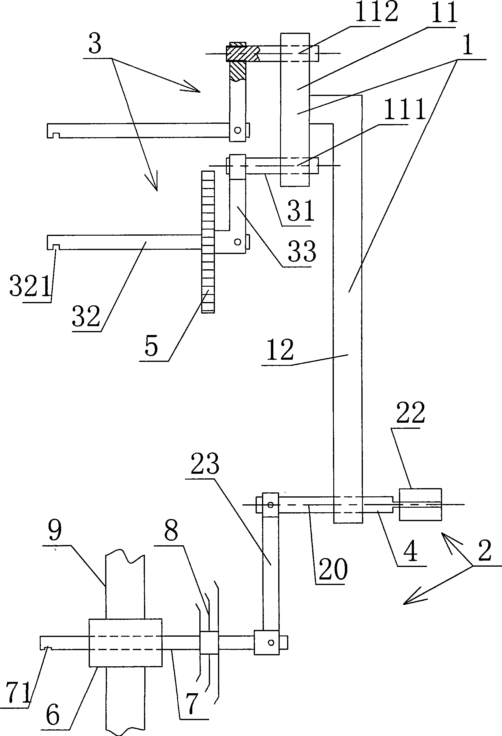
[0022] Such as figure 2 As shown, the difference between Embodiment 2 and Embodiment 1 is that the pedal or the handle 22 is directly connected to the outer end of the power end connecting rod 4 in rotation, instead of being connected with the power end connecting rod 4 through the swing arm 21 .

Embodiment 3

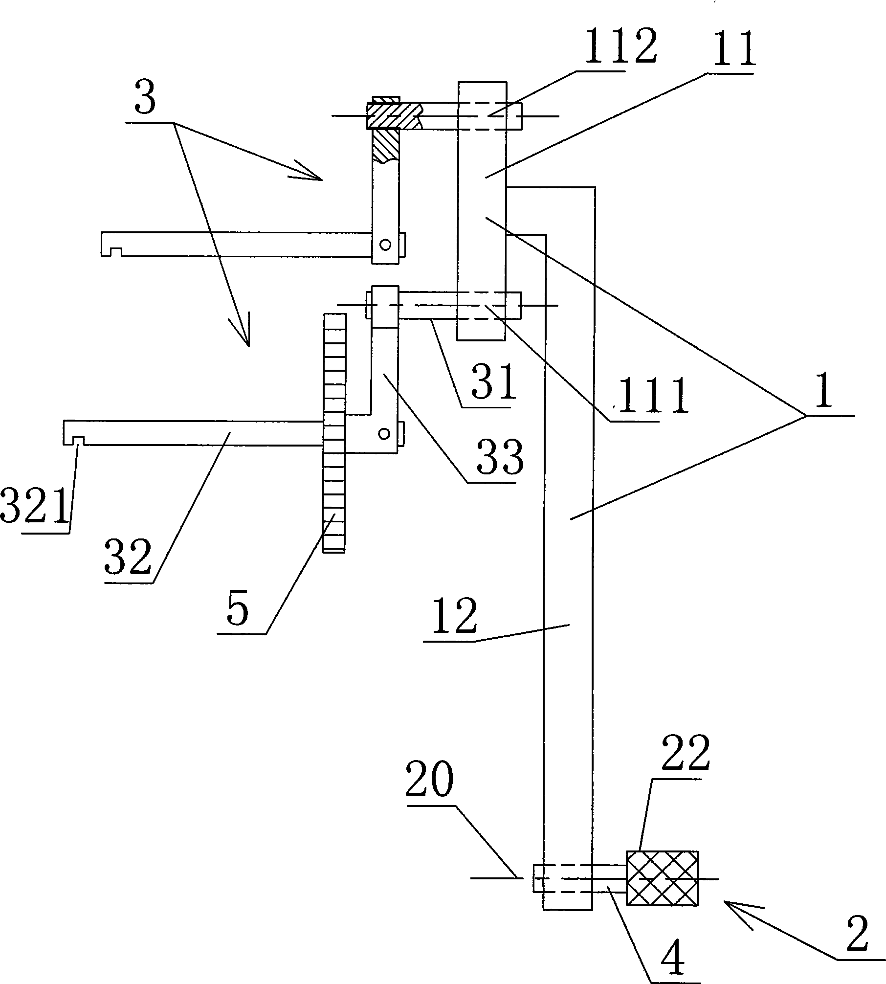
[0024] Such as image 3 As shown, the difference between embodiment 3 and embodiment 1 is that the pedal or handle device 2 is connected to the power rod 12 through the power end connecting rod 4, and the pedal or handle device 2 is only connected to the power end connecting rod 4 A pedal or handle 22 at the outer end constitutes.


PUM


Abstract

The invention relates to a labor-saving driving device of a bicycle, which comprises a driving piece, a pedal or a handle device and a pair of Z-shaped connecting rods, wherein the connecting action center line of the pedal or the handle device and the driving piece and the connecting action center line of the two Z-shaped connecting rods and the driving piece are mutually parallel, each Z-shaped connecting rod comprises a vertical rod and a pair of parallel transverse rods, the second transverse rod is rotationally connected with a bicycle frame, the shaft center distances of the corresponding transverse rods of the two Z-shaped connecting rods are the same, the driving piece comprises a connecting plate and a driving rod, the first cross rods of the two Z-shaped connecting rods are respectively rotationally connected with both ends of the connecting plate, one end of a power rod is fixedly connected in the middle part of the connecting plate, the other end of the power rod is connected with the pedal or the handle device, the connecting positions of the two first cross rods and the connecting plate are respectively positioned on both sides of the fixed connecting position of the power rod and the connecting plate, and one Z-shaped connecting rod is fixedly connected with a driving chain disk. The device not only can more conveniently and freely rotate the Z-shaped connecting rods, but also can further improve the labor-saving effect.

Description

technical field [0001] The invention belongs to the technical field of non-motor vehicles, namely bicycles, tricycles and other vehicles, and more specifically relates to a bicycle labor-saving transmission device for non-motor vehicles. Background technique [0002] Due to the limitation of the pedaling position of the existing common bicycle, the length of the single-arm lever used to be connected with the pedal on the chain plate is relatively short, which is not too labor-saving. A Chinese Utility Model Patent No. 200620158888.2 filed by the applicant of the present invention on November 9, 2006 discloses a "bicycle labor-saving transmission part". The bicycle moves forward: the first connection point and the second connection point of the transmission rod are respectively connected to the two "Z"-shaped connecting rods in rotation, and the third connection point is connected to the pedal or the handle device. The force makes the three connection points of the transmiss...

Claims


Application Information

Patent Timeline
IPC IPC(8): B62M3/00
CPCB62M15/00
Inventor 韩东平
Owner 韩东平
Why Eureka
Try Eureka