Boosting clamp

A force-increasing and clamping technology, which is applied in the direction of clamps, manufacturing tools, etc., to achieve the effect of convenient operation and compact structure

Active Publication Date: 2013-05-01
HANGZHOU GREAT STAR TOOLS
View PDF0 Cites 0 Cited by
  • Summary
  • Abstract
  • Description
  • Claims
  • Application Information

AI Technical Summary

Problems solved by technology

However, the object can only be clamped to a certain extent by means of the afterburner handle. If further clamping is required, the user is helpless

Method used


Image

  • Boosting clamp
  • Boosting clamp
  • Boosting clamp

Examples


Embodiment Construction

[0026] The present invention will be further described below through a preferred embodiment in conjunction with the accompanying drawings.

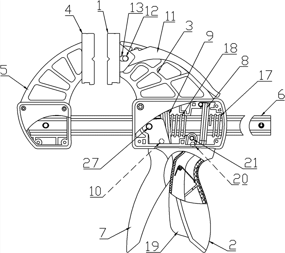
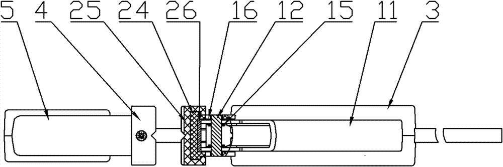
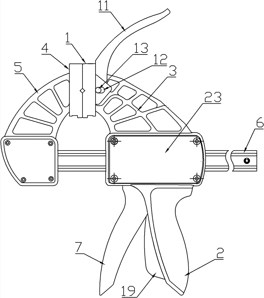
[0027] Such as Figure 1-2 As shown, the booster clamp of the present invention includes a fixed clamp body 3 with a fixed chuck 1 and a handle 2, a movable clamp body 5 with a movable chuck 4, a guide rod 6, and a booster handle 7 (as a connection method , the booster handle 7 is connected to the fixed clamp body 3 through the pin shaft 27), the guide rod 6 is penetrated on the fixed clamp body 3, and the guide rod 6 is equipped with a locking clip 8 and a booster clip 9 (in the figure The shown locking clip 8 and the force clip 9 are respectively a group, which can be one piece during specific implementation), and the movable clip body 5 is installed (it can be fixed or detachable, and can be replaced when it is detachable) to the other end of the guide rod to support the object) at the left end of the guide rod 6 and the fixed chuck 1...


PUM


Abstract

The invention discloses a boosting clamp. The traditional clamp is difficult to further clamp an article after clamping the article to a certain extent through a stress application handle. The boosting clamp comprises a fixed clamp body with a fixed chuck and a grip, a moving clamp body with a moving chuck, a guide rod and the stress application handle, wherein the guide rod is penetrated on the fixed clamp body, and a locking clamping piece and a stress application clamping piece are configured for the guide rod; the moving clamp body is arranged at one end of the guide rod, and the fixed clamp body and the moving clamp body correspond; the stress application handle and the grip are correspondingly arranged and the stress application handle is provided with a stress application part usedfor pushing the stress application clamping piece; one of the fixed chuck and the moving chuck is movably connected with the corresponding clamp body; and the clamp body is provided with a boosting handle for boosting the movably connected chuck. Through additionally arranging the boosting handle, after the article is clamped to a certain extent by the stress application handle, the article can be further clamped through the boosting handle.

Description

technical field [0001] The invention relates to a clamp, in particular to a booster clamp which increases the clamping force on the object through the booster handle after the initial clamping of the object by the booster handle. Background technique [0002] The existing fixture includes a fixed clip body, a movable clip body, a guide rod, and a booster handle. The guide rod is equipped with a locking clip and a booster clip, and the booster clip is driven by the booster handle to pass through the fixed The guide rod on the clip body moves to change the distance between the fixed clip body and the movable clip body to realize the clamping of the object. However, the object can only be clamped to a certain extent by the force-reinforcing handle, and if further clamping is required, the user is helpless. Contents of the invention [0003] The technical problem to be solved and the technical task proposed by the present invention is the defect that the existing clamp is dif...

Claims


Application Information

Patent Timeline
Patent Type & Authority Patents(China)
IPC IPC(8): B25B5/04B25B5/16
Inventor 李跃明
Owner HANGZHOU GREAT STAR TOOLS
Why Eureka
Try Eureka