Motor and motor integrated pump with the motor

A motor and motor-driven technology, applied in the direction of pumps, pump devices, mechanical equipment, etc., can solve the problems of position deviation, winding and wiring operation obstacles, etc., and achieve the effect of reducing manufacturing costs, shortening takt time, and easy wiring operations.

Active Publication Date: 2009-07-29
MATSUSHITA ELECTRIC WORKS LTD
View PDF1 Cites 8 Cited by
  • Summary
  • Abstract
  • Description
  • Claims
  • Application Information

AI Technical Summary

Problems solved by technology

[0006] However, in the above-mentioned Patent Document 1, since there is no part for fixing the connection structure and the insulator, it is possible to pr

Method used


Image

  • Motor and motor integrated pump with the motor
  • Motor and motor integrated pump with the motor
  • Motor and motor integrated pump with the motor

Examples


Example Embodiment

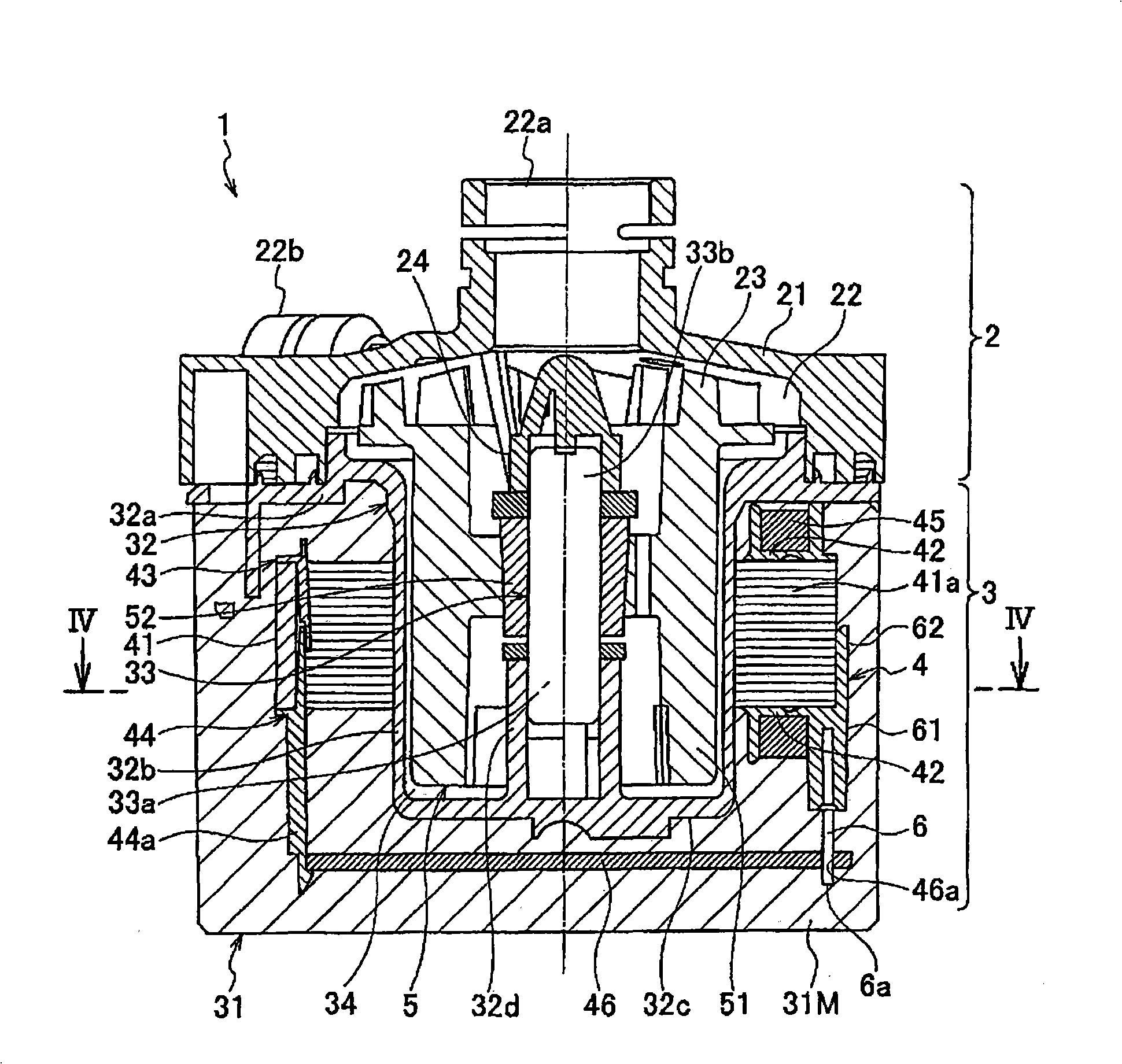
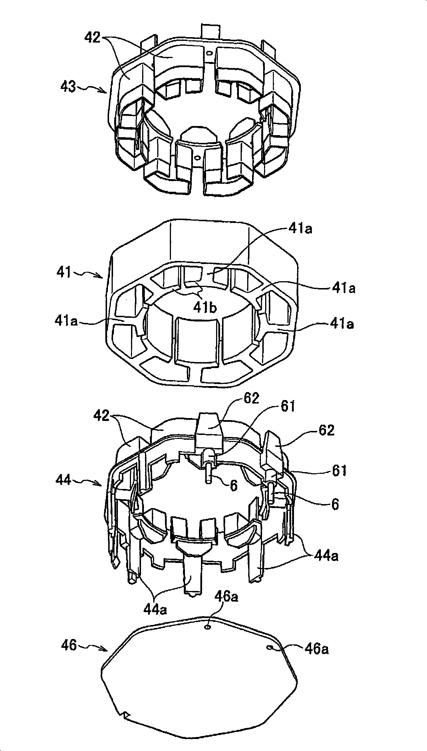
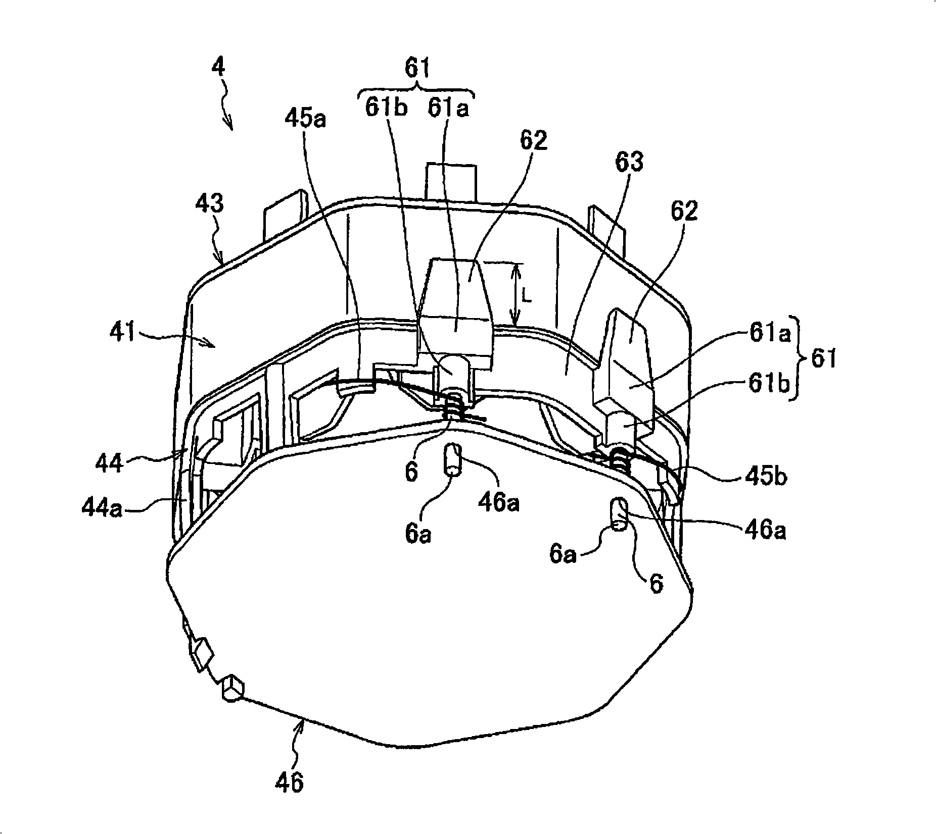
[0023] Hereinafter, embodiments of the present invention will be described in detail with reference to the drawings. Figure 1 ~ Figure 5 A motor-integrated pump according to an embodiment of the present invention is shown. among them, figure 1 Is a cross-sectional view of the motor-integrated pump according to this embodiment, figure 2 Is an exploded perspective view of the stator, image 3 Is a perspective view showing the assembled state of the stator, Figure 4 Is along figure 1 A cross-sectional view of the IV-IV line in, Figure 5 Yes Figure 4 An enlarged cross-sectional view of the V section in.

[0024] Such as figure 1 As shown, the motor-integrated pump 1 includes a pump 2 and a motor 3. In the pump chamber 22 of the pump housing 21, an impeller 23 constituting a centrifugal pump is rotatably housed. In addition, a suction port 22 a is formed in the center of the pump chamber 22, and a discharge port 22 b is formed in the tangential direction of the peripheral edge ...


PUM


Abstract

The invention provides a motor of wiring operation capable of winding more easily and reliably, and a motor-integrated pump equipped with the motor. At least two pins (6) are arranged for binding two end parts (45a,45b) of a winding (45) and clamping a front end part (6a) into a hole (46a) formed on a control substrate (46); a mounting part (61) is laterally protruded toward the control substrate (46) on an insulator (44), and respectively fixes the pin (6) under the condition of laterally protruding toward the control substrate (46); a strengthening wall (63) is laterally protruded toward the control substrate (46) on an insulator (44) and mutually connects between the mounting parts (61,61); further, a strengthening rib (62), which is abutted against the peripheral of a stator core (41, is arranged on the mounting part (61).

Description

technical field [0001] The present invention relates to a motor and a motor-integrated pump including the motor. Background technique [0002] As a conventional motor, there is known a motor that includes a stator core (stator core) formed by laminating a plurality of stator iron plates, and a plurality of teeth portions are provided at equal intervals in the circumferential direction on the inner periphery of the stator core. structure (for example, refer to Patent Document 1). [0003] In Patent Document 1, insulators are respectively provided on both ends in the axial direction of the central axis of the stator core, and a plurality of covering portions covering the outer sides of each tooth portion are provided on each insulator at equal intervals in the circumferential direction. (comb engaging part). And, a winding wire is wound around the tooth portion covered by the covering portion. That is, while ensuring insulation between the teeth (stator core) and the windin...

Claims


Application Information

Patent Timeline
IPC IPC(8): H02K3/46F04D13/06
CPCH02K3/26H02K3/345H02K3/38H02K37/04
Inventor 福田哲也阿南哲也德永亮平
Owner MATSUSHITA ELECTRIC WORKS LTD
Why Eureka
Try Eureka