Method for the controlled purging of the fuel feeding system in the combustor of a gas turbine engine

A fuel supply system, gas turbine technology, applied in the direction of turbine/propulsion fuel delivery system, combustion method, gas turbine device, etc.

Inactive Publication Date: 2009-09-16
NUOVO PIGNONE SPA
View PDF4 Cites 3 Cited by
  • Summary
  • Abstract
  • Description
  • Claims
  • Application Information

AI Technical Summary

Problems solved by technology

The purge phase using air also requires relatively long start and stop times, since the system must be activated gradually t

Method used


Image

  • Method for the controlled purging of the fuel feeding system in the combustor of a gas turbine engine
  • Method for the controlled purging of the fuel feeding system in the combustor of a gas turbine engine
  • Method for the controlled purging of the fuel feeding system in the combustor of a gas turbine engine

Examples


Embodiment Construction

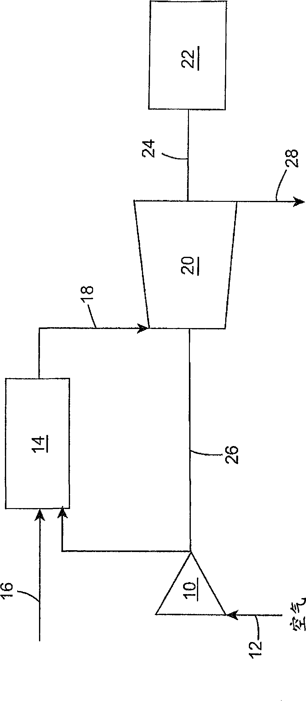
[0016] especially refer to figure 1 , shows a schematic diagram of a general gas turbine, preferably of the twin-shaft type, comprising a compressor 10 capable of compressing air introduced through an inlet 12 . The compressed air is then sent to the combustor 14 to mix with the gaseous fuel from the supply conduit 16 . Combustion increases the temperature, velocity and volume of the gas stream and thus increases the energy contained therein. The gas flow is directed through a duct 18 leading to a turbine 20 , which converts the gas energy into work energy that can be used to start a working machine, such as an electrical generator 22 connected to the turbine 20 by a shaft 24 . Turbine 20 also supplies the necessary energy to start compressor 10 via shaft 26 , while exhaust gas is discharged by turbine 20 via exhaust duct 28 .

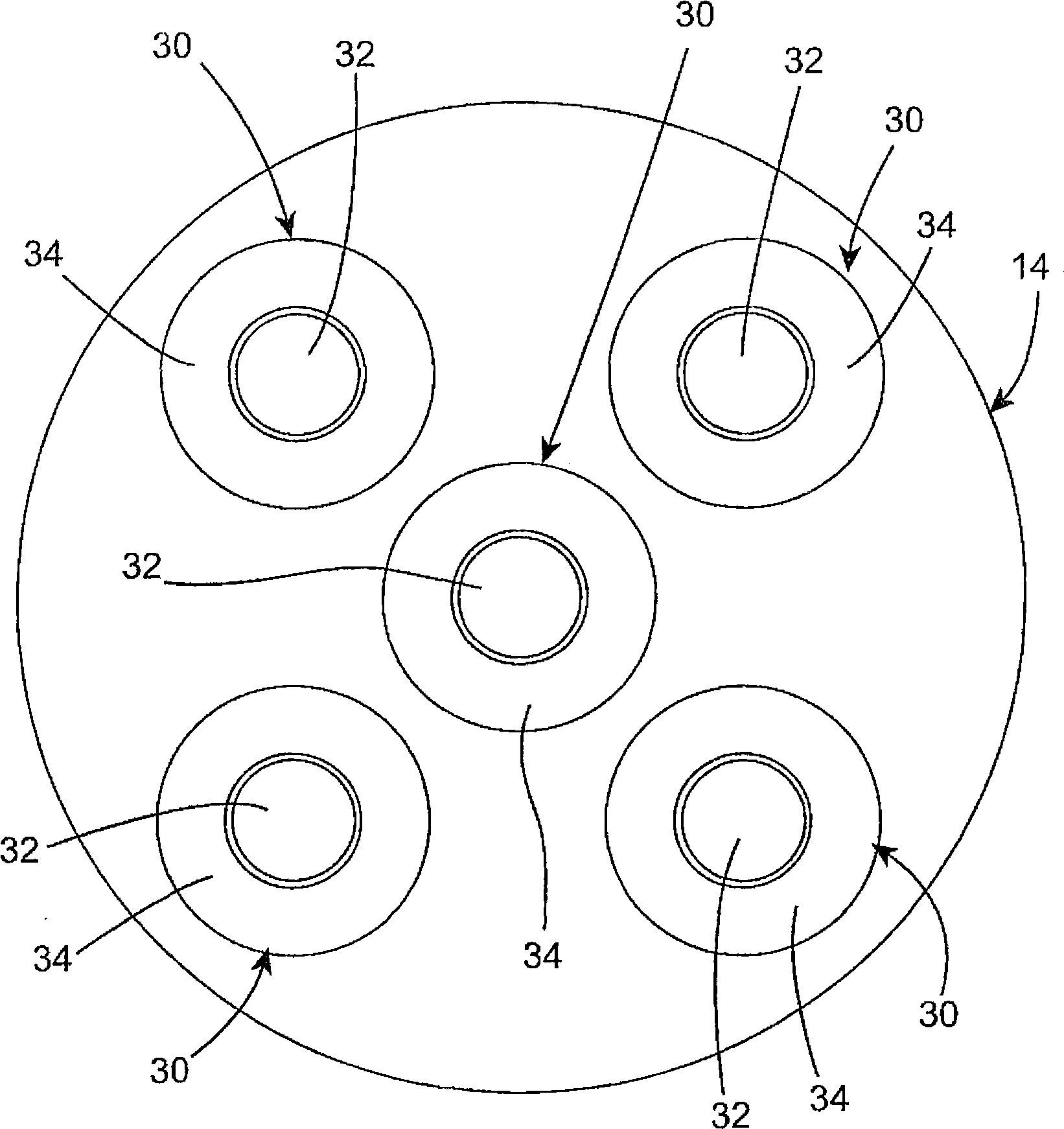
[0017] figure 2 A transverse cross-section of an exemplary multi-tube combustor 14 is schematically illustrated according to an exemplary embodime...


PUM


Abstract

A method is described for the controlled purging of the fuel feeding system in the combustor of a gas turbine comprising at least one compressor (10), capable of compressing the air introduced into it through an inlet duct (12), at least one combustor (14), in which said compressed air is mixed and combusted with a gaseous fuel coming from a feeding duct (16), and at least one turbine (20), capable of transforming the energy of the combusted gas coming from said combustion chamber (14) into work energy which can be exploited for activating one or more operating machines (22). The combustor (14) is equipped with one or more burners (30), each equipped with at least one pilot injector (36) and one or more main injectors (38) for the adduction of the gaseous fuel inside the burner (30). The method comprises purging at least part of the main injectors (38) and relative manifolds (34) with a stream of gaseous fuel when the turbine is in diffusive flame functioning mode and purging the pilot injector (36) and relative manifold (32) with a stream of gaseous fuel when the turbine is in premixed flame functioning mode.

Description

technical field [0001] Exemplary embodiments generally relate to a method for controlled purge of a fuel supply system in a combustor of a gas turbine. Background technique [0002] The use of a gas turbine typically includes a multistage compressor where air drawn in from the outside is compressed; a combustor where combustion occurs of a gaseous fuel added to the compressed air; and a turbine or expander where gas from the combustor is compressed Expansion, which is known as the generation of electrical energy. Thus, the turbine is capable of generating mechanical energy for driving a working machine or for charging an electrical generator, such as one or more alternators. [0003] Combustors currently used in gas turbines can be differentiated based on two types of functionality. The first type of function is the so-called "diffusion flame", in which air and gaseous fuel are admitted to the combustion device separately, according to the traditional design of turbines st...

Claims


Application Information

Patent Timeline
IPC IPC(8): F02C7/00F02C7/22
CPCF23R3/286F02C7/228F23D2209/30F23R3/343
Inventor G·通诺A·阿斯蒂A·巴尔达萨尔M·贝蒂M·德尔科尔M·佩奇S·里瓦J·斯图尔特
Owner NUOVO PIGNONE SPA
Why Eureka
Try Eureka