Compensating three-phase active power factor correcting circuit

A power factor correction and correction circuit technology, applied in reactive power compensation, reactive power adjustment/elimination/compensation, energy industry, etc. Product performance and market competitiveness, high input power factor and power density, cost reduction effect

Active Publication Date: 2009-09-23
VERTIV CORP
View PDF0 Cites 15 Cited by
  • Summary
  • Abstract
  • Description
  • Claims
  • Application Information

AI Technical Summary

Problems solved by technology

image 3 It shows that the three-phase input current Ia, Ib, Ic of the uncontrolled three-phase active power factor correction circuit is similar to the input voltage waveform only in the waveform part, and the corresponding input current near the zero-crossing phase of the input voltage of this phase is zero , resulting in the input current waveform not being fully sinusoidal, resulting in a relatively low input power factor, and figure 2 The stand-alone three-phase active power factor correction circuit shown is an obvious flaw compared to

Method used


Image

  • Compensating three-phase active power factor correcting circuit
  • Compensating three-phase active power factor correcting circuit
  • Compensating three-phase active power factor correcting circuit

Examples


specific Embodiment approach 1

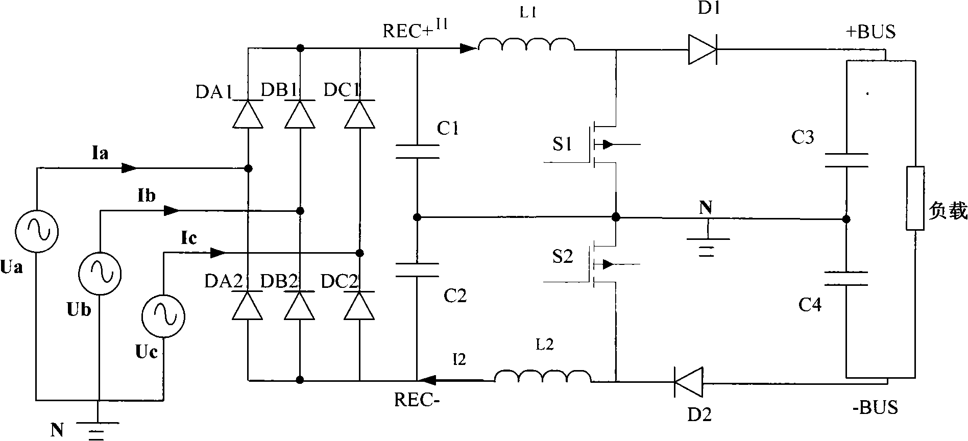
[0034] Such as Figure 4 The shown compensated three-phase active power factor correction circuit includes an uncontrolled three-phase active power factor correction circuit 1, which is a three-phase circuit composed of six diodes DA1, DA2, DB1, DB2, DC1, and DC2. Uncontrolled rectifier bridge, two MOSFET switch tubes S1 and S2 for power conversion, two filter capacitors C1 and C2 respectively connected to the two output terminals of the three-phase uncontrolled rectifier bridge, two boost inductors L1, L2 and two A three-phase double-switch power factor correction circuit with positive and negative output filter capacitors C3, C4 and output diodes D1, D2 respectively connected to both ends of the load. One end of the boost inductor L1, L2 is respectively connected to an output end of the three-phase uncontrolled rectifier bridge, and the other end is respectively connected to one end of the output diode D1, D2.

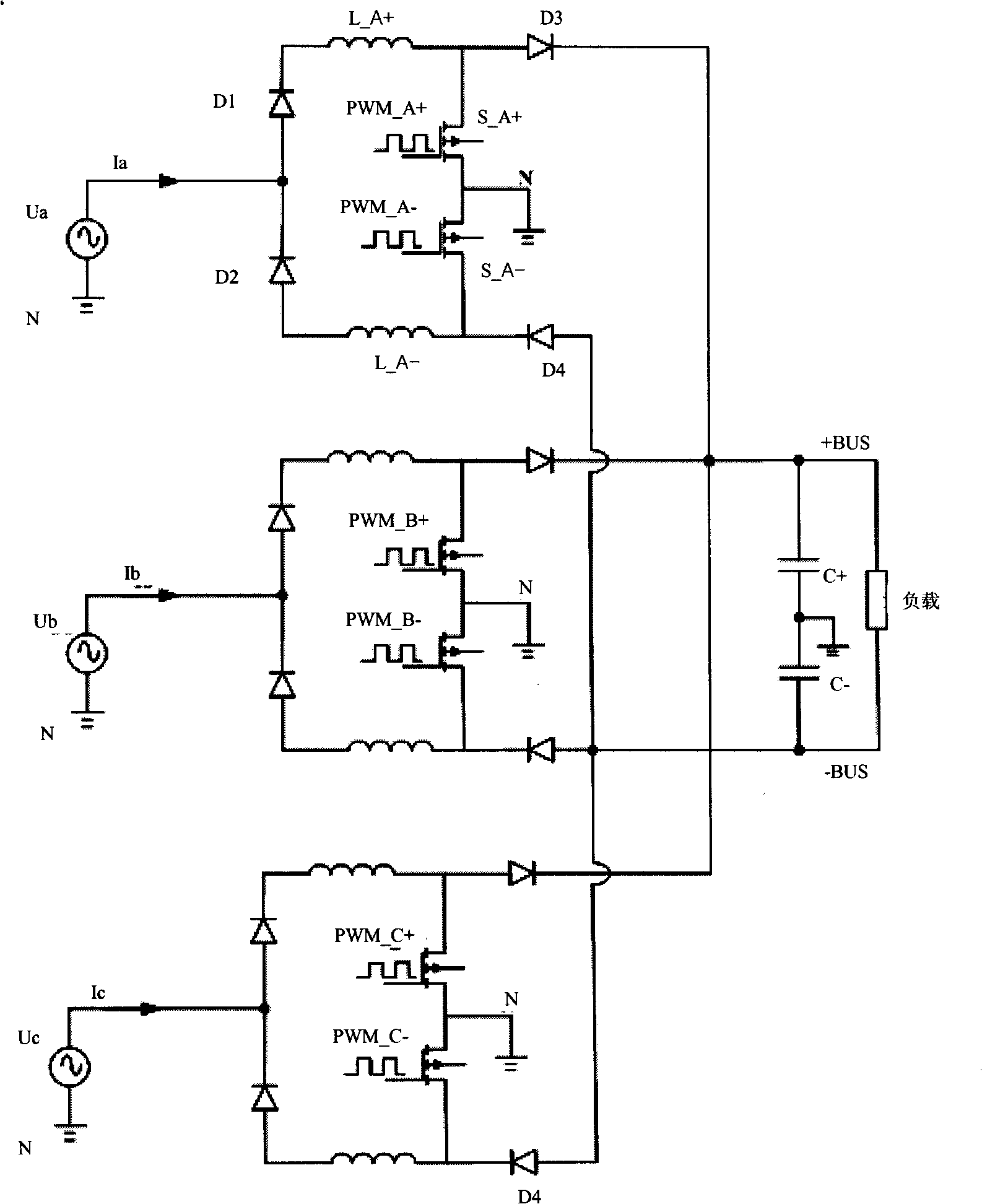
[0035] There is a three-phase compensation circuit 2-controlla...

specific Embodiment approach 2

[0053] Such as Figure 8 The compensation type three-phase active power factor correction circuit shown is different from the circuit of the specific embodiment 1 in that: the three-phase compensation circuit 2 - the controllable three-phase double-switch power factor correction circuit omits the step-up for power conversion The three input ends of piezoelectric inductors L3 and L4 are respectively connected to one end of three boost inductors L5, L6, and L7, and the other ends of three boost inductors L4, L5, and L6 are respectively connected to three-phase input voltage sources Ua, Ub and Uc are connected. The same compensation function as that of the circuit in Embodiment 1 can also be realized by adding an inductor. Although an inductor is added, the effective value of the current flowing through a single inductor is smaller than that of Embodiment 1, and the volume of the inductor can be smaller under the same inductance value.

specific Embodiment approach 3

[0054] Such as Figure 9 The compensation type three-phase active power factor correction circuit shown is suitable for three-phase input power grid voltage quality is very good, power factor correction without high-frequency interference. The difference from the circuit in Embodiment 1 is: the uncontrolled three-phase active power factor correction circuit 1 and the three-phase compensation circuit 2-the controllable three-phase double-switch power factor correction circuit respectively omits the filter input market Filter capacitors C1 and C2 for electric high-frequency clutter, and filter capacitors C5 and C6. The same compensation function as that of the circuit in the first embodiment can be realized.


PUM


Abstract

The invention discloses a compensating three-phase active power factor correcting circuit, which comprises an uncontrolled three-phase active power factor correcting circuit, and is characterized in that the compensating three-phase active power factor correcting circuit is provided with a three-phase compensating circuit, namely a controllable three-phase double-switch power factor correcting circuit; three input ends of the controllable three-phase double-switch power factor correcting circuit are connected with three input ends of the uncontrolled three-phase active power factor correcting circuit; and two output ends of the controllable three-phase double-switch power factor correcting circuit are connected with two output ends of the uncontrolled three-phase active power factor correcting circuit. The compensating three-phase active power factor correcting circuit combines respective advantages of independent and uncontrolled three-phase active power factor correcting circuits, can keep sine wave forms of input current and corresponding input voltage similar and phases same, achieves full sine of three-phase input current, has higher input power factor and power density, effectively reduces 'pollution' of a switch power supply on an electric network, and also can obviously reduce the number of switch power supply devices, the volume of the switch power supply and the cost of the switch power supply and further improve product performance and market competitiveness.

Description

technical field [0001] The invention relates to a power factor correction circuit, in particular to a compensation type three-phase active power factor correction circuit. Background technique [0002] Switching power supply is a power electronic device that provides DC power for computers, communications and household electronic equipment. According to the power conversion method, it is classified into two types: AC / DC and DC / DC. The traditional three-phase AC / DC power conversion input stage generally adopts diode rectification plus capacitor filter circuit, the input current waveform is in the shape of a sharp pulse, and a large number of harmonic components flow back into the grid, causing harmonic "pollution" to the input grid, and must be used The active power factor correction circuit (Active Power Factor Correction, referred to as APFC) controls the input current waveform to be similar to the sinusoidal waveform of the input voltage to reduce the current harmonic cont...

Claims


Application Information

Patent Timeline
Patent Type & Authority Applications(China)
IPC IPC(8): H02J3/18
CPCY02E40/30Y02P80/10
Inventor 张春涛肖学礼张晓飞
Owner VERTIV CORP
Why Eureka
Try Eureka