Device for controlling electric vehicle and electric vehicle equipped with the control device, and electric vehicle control method and computer readable recording medium on which program for allowing

A technology for electric vehicles and control devices, applied in vehicle energy storage, AC motor control, single motor speed/torque control, etc., can solve problems such as converter overheating and converter loss increase, and achieve suppression of current concentration and reduction Effect of conduction loss and prevention of overheating damage

Active Publication Date: 2010-01-06
DENSO CORP
View PDF6 Cites 11 Cited by
  • Summary
  • Abstract
  • Description
  • Claims
  • Application Information

AI Technical Summary

Problems solved by technology

[0003] In such an electric vehicle, for example, when the driving torque and vehicle weight are balanced when going uphill, so-called "motor lock state" (a state in which the motor torque is output but the motor speed is extremely low), due to the concentrated current flowing into the The loss of the converter increases due to the specific phase, and the converter may overheat in a short time

Method used


Image

  • Device for controlling electric vehicle and electric vehicle equipped with the control device, and electric vehicle control method and computer readable recording medium on which program for allowing
  • Device for controlling electric vehicle and electric vehicle equipped with the control device, and electric vehicle control method and computer readable recording medium on which program for allowing
  • Device for controlling electric vehicle and electric vehicle equipped with the control device, and electric vehicle control method and computer readable recording medium on which program for allowing

Examples


Embodiment approach 1

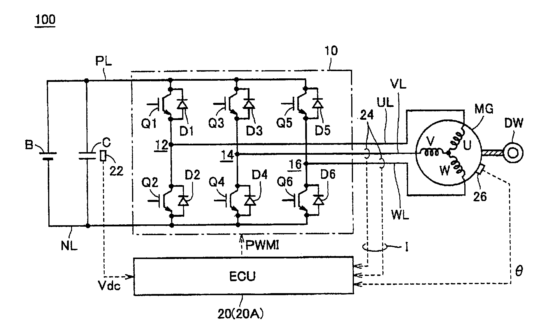
[0107] figure 1 It is a diagram showing the powertrain configuration of the electric vehicle according to Embodiment 1 of the present invention. refer to figure 1 , the electric vehicle 100 includes a power storage device B, an inverter (inverter) 10 , an electronic control unit (hereinafter referred to as “ECU (Electronic Control Unit)”) 20 , a motor generator MG, and wheels DW. Electric vehicle 100 also includes positive line PL, negative line NL, capacitor C, U-phase line UL, V-phase line VL, and W-phase line WL. Furthermore, electric vehicle 100 further includes a voltage sensor 22 , a current sensor 24 , and a rotation angle sensor 26 .

[0108] The positive terminal and negative terminal of power storage device B are connected to positive line PL and negative line NL, respectively. Capacitor C is connected between positive line PL and negative line NL. Inverter 10 includes a U-phase arm 12 , a V-phase arm 14 , and a W-phase arm 16 . U-phase arm 12 , V-phase arm 14 ,...

Embodiment approach 2

[0161] As described above, in the motor lock state in which the motor rotation speed is extremely low, a thermally severe situation remarkably occurs due to current concentration in a specific phase. Therefore, in the second embodiment, the variable control of the PWM center is executed when the switching frequency of the inverter is low and the motor lock state is detected.

[0162] According to the drive train structure of the electric vehicle according to Embodiment 2, the figure 1 The illustrated electric vehicle 100 according to Embodiment 1 is the same.

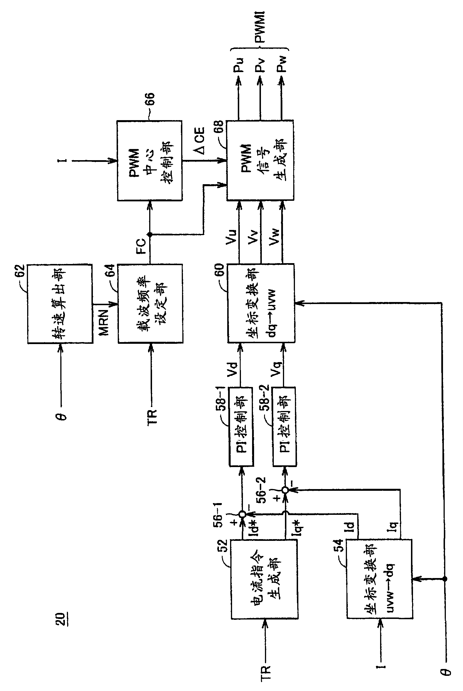
[0163] Figure 13 It is a functional block diagram of ECU20A in Embodiment 2. refer to Figure 13 , ECU20A in figure 2 In the configuration of the ECU 20 in Embodiment 1 shown, a PWM center control unit 66A is included instead of the PWM center control unit 66 .

[0164] PWM center control unit 66A receives motor rotation angle θ and motor rotation speed MRN from rotation speed calculation unit 62 , and receives c...

Embodiment approach 3

[0174] In Embodiment 3, an example of the amount of change of the PWM center when the motor is locked is shown. Specifically, in Embodiment 3, the PWM center is changed so as to reduce the conduction loss of the phase with the largest current and balance the conduction loss of each phase.

[0175] The overall structures of the electric vehicle and the ECU according to Embodiment 3 are respectively the same as figure 1 The electric vehicle 100 and Figure 13 The ECU 20A shown is the same. Hereinafter, a method of determining a PWM center in Embodiment 3 will be described.

[0176] Now, suppose for Figure 12 The motor lock state occurs at the motor rotation angle θ1 shown (when the U-phase motor current Iu is the peak value). In addition, it is assumed that the diodes D1 to D6 have more thermal margin than the transistors Q1 to Q6.

[0177] Loss ΔLu of transistor Q1 in the U-phase upper arm can be represented by the following equation.

[0178] ΔLu=∫(V CE × I CE )dt+∫(V...


PUM


Abstract

A carrier frequency setting unit (64) sets a carrier frequency (FC) based on a torque command (TR) and a motor rotation number (MRN) of a motor generator. A PWM signal producing unit (68) produces phase modulated waves corresponding to respective phase voltage commands (Vu, Vv and Vw), and produces respective phase PWM signals (Pu, Pv and Pw) corresponding to a relationship in magnitude between the respective phase modulated waves and a carrier having the carrier frequency (FC). A PWM center control unit (66) produces a PWM center correction value ( CE) for variably controlling the PWM center when the carrier frequency (FC) is lower than a predetermined frequency, and provides the same to the PWM signal producing unit (68).

Description

technical field [0001] The present invention relates to a control technology of an electric vehicle equipped with an AC motor as a power source for vehicle running. Background technique [0002] In recent years, electric vehicles such as electric vehicles, hybrid vehicles, and fuel cell vehicles have attracted attention against the background of environmental problems. Many of these electric vehicles are equipped with an AC motor driven by an inverter (inverter) as a power source for vehicle running. [0003] In such an electric vehicle, for example, when the driving torque and vehicle weight are balanced when going uphill, so-called "motor lock state" (a state in which the motor torque is output but the motor speed is extremely low), due to the concentrated current flowing into the Due to the specific phase, the loss of the converter increases, and the converter may overheat in a short time. [0004] Then, Japanese Patent Application Laid-Open No. 2002-272125 (Patent Docu...

Claims


Application Information

Patent Timeline
Patent Type & Authority Applications(China)
IPC IPC(8): H02P6/08H02P6/12H02P27/06B60L3/00B60L9/18H02M7/48B60W10/08B60W20/00B60L50/13
CPCH02P21/06Y02T10/643B60L15/025B60L11/08H02P27/08Y02T10/7077Y02T10/642Y02E10/56H02P27/085H02M7/53875H02M7/5395H02P23/08H02P23/28B60L50/13Y02T10/64Y02T10/7072H02M1/0025H02M1/32H02M1/327Y02T10/70
Inventor 冈村贤树野泽奈津树花田秀人
Owner DENSO CORP
Why Eureka
Try Eureka