Linear isolating circuit based on optical couplers and method

A linear isolation circuit, isolation circuit technology, applied in the direction of logic circuit connection/interface layout, etc., can solve the problems of complex isolation circuit structure, high cost, not suitable for the application of analog signal input with high measurement voltage, etc., to improve the feedback quality. , the effect of improving safety and reducing impact

CN101645708BActive Publication Date: 2011-10-05叶克江
0 Cites 0 Cited by

Patent Information

Authority / Receiving Office
CN · China
Patent Type
Patents(China)
Current Assignee / Owner
Publication Date
2011-10-05

Smart Images

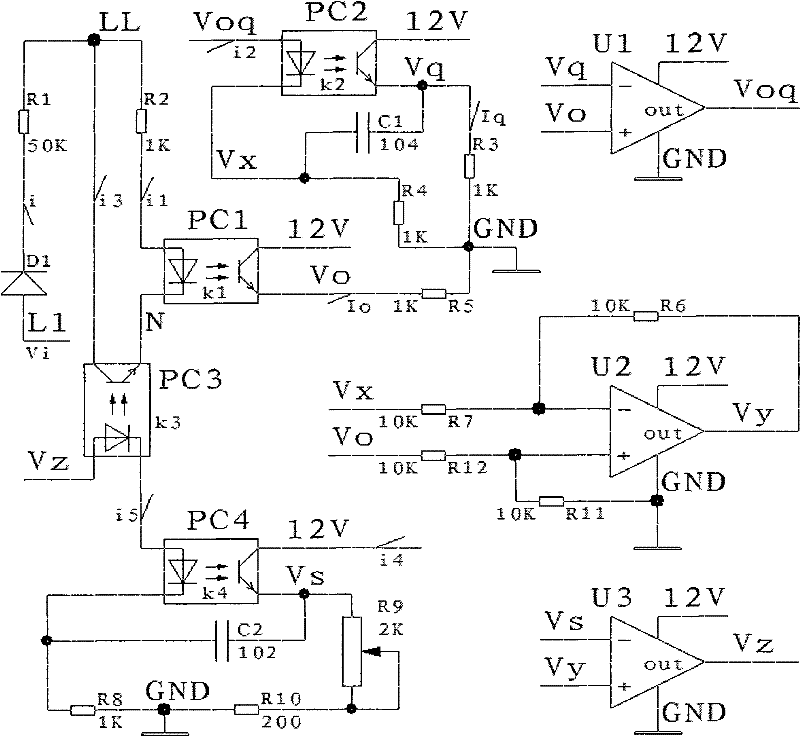
  • Figure 1
    Figure 1
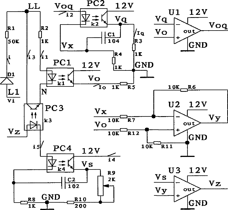
  • Figure 2
    Figure 2
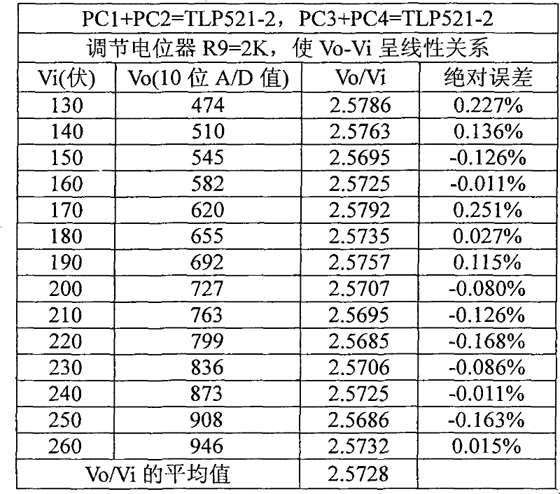
  • Figure 3
    Figure 3
Patent Text Reader

Abstract

The invention relates to a linear isolating circuit based on optical couplers and a method, wherein the circuit comprises an input and output optical coupler PC1, a first voltage follower, a sampling optical coupler PC2, a subtracter, a second voltage follower, a feedback optical coupler PC3 and a comparing optical coupler PC4, wherein the input and output optical coupler PC1 is connected with the input end of the isolating circuit in series; the first voltage follower is used for following the output voltage of the optical coupler PC1; the sampling optical coupler PC2 is used for sampling the practical input current of a photoreceptor of the optical coupler PC1; the subtracter is used for computing the subtraction of the output voltage of the photoreceptor of the optical coupler PC1 and the cathode voltage of an illuminating device of the optical coupler PC2; the second voltage follower is used for following the output voltage of the subtracter; the feedback optical coupler PC3 is used for feeding the feedback comparing control current of the second voltage follower and the optical coupler PC4 to the input end of the isolating circuit; an illuminating device of the comparing optical coupler PC4 is connected with an illuminating device of the optical coupler PC3 in series; the optical coupler PC1 is matched with the optical coupler PC2; the optical coupler PC3 is matched with the optical coupler PC4 and the current transmission of the optical coupler PC1 is larger than 1. The linear isolating circuit has the advantages of simple structure, high precision, good linear degree, low cost, high safety and the like.
Need to check novelty before this filing date? Find Prior Art

Description

technical field

[0001] The invention relates to a linear isolation technology based on an optocoupler (optocoupler for short), in particular to a linear isolation circuit and method based on an optocoupler. Background technique

[0002] There are many traditional methods for linear isolation of analog signals. The use of optocouplers to achieve linear isolation of electrical signals has certain advantages in terms of volume, cost, anti-interference ability, and circuit complexity, so it has been widely used. Its function is to avoid the error caused by the different grounding points of the input terminal (signal terminal) and the output terminal circuit, the second is to protect the output terminal circuit from the influence of the input terminal circuit failure, and the third is to provide strong anti-interference ability. The isolation achieved by optocoupler is divided into digital signal isolation and analog signal isolation. The optocoupler isolation method for digita...

Examples

Embodiment

[0024] Such as figure 1 As shown, the present invention mainly includes 4 common optocouplers PC1, PC2, PC3, PC4 and 3 road operational amplifiers U1, U2 and U3, resistors R1, R2, R3, R4, R5, R6, R7, R8, R9, R10 , R11, R12. The emitters of the 4 ordinary optocouplers all use light-emitting diodes, and the light receivers all use phototransistors. Among them, PC1 is called the input and output optocoupler, PC2 is called the sampling optocoupler, PC3 is called the feedback optocoupler, and PC4 is called the feedback optocoupler. For comparison optocouplers. The light emitter of the input and output optocoupler PC1 is connected in series with the input terminal of the isolation circuit, and the emitter output terminal Vo of the light receiver is connected with the non-inverting input terminal of the first voltage follower U1; the sampling optocoupler PC2 is passed through the first voltage follower U1. The forced following function of the voltage of the non-inverting input termi...