Magnetic flow convertor with permanent magnet

A magnetic flux converter and permanent magnet technology, applied to the power device inside the switch, the protection switch operation/release mechanism, etc., can solve the problems of complex structure, large volume, and complicated production process of the shell and cover, and achieve high use Value, good economic benefits, and the effect of reducing production costs

Active Publication Date: 2011-07-20
浙江中凯科技股份有限公司
View PDF1 Cites 2 Cited by
  • Summary
  • Abstract
  • Description
  • Claims
  • Application Information

AI Technical Summary

Problems solved by technology

The device includes all the components of the magnetic flux converter. The structure of the shell and the cover is complicated, and the production process of the whole device is complicated. Because it includes permanent magnets, tripping coils, armatures, ejector rods and other parts, the volume is relatively large.

Method used


Image

  • Magnetic flow convertor with permanent magnet
  • Magnetic flow convertor with permanent magnet
  • Magnetic flow convertor with permanent magnet

Examples


Embodiment Construction

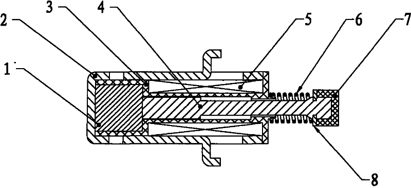
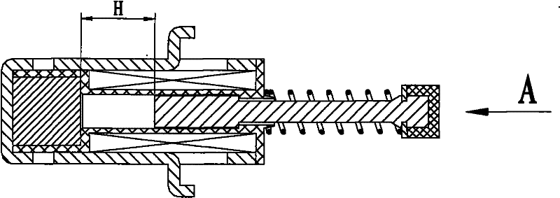
[0019] refer to figure 1 , which is a structural schematic diagram of a magnetic flux converter in the pull-in position of the present invention.

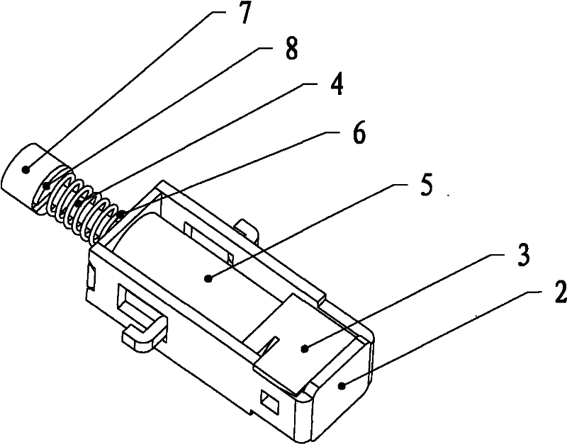
[0020] As shown in the figure, it is an embodiment, including a U-shaped magnetic yoke (2) with symmetrical fixed claws on both sides. The magnetic yoke is equipped with a bobbin (3), ejector rod (4), coil (5), and a permanent magnet. (1) is fixed between the U-shaped yoke (2) and a part of the bobbin (3). Also housed in the coil bobbin (3), and a step hole is designed to prevent the push rod (4) from protruding. Push rod (4) is equipped with, jump ring (8) and buffer pad (7).

[0021] figure 1 What is shown is that the magnetic flux converter is in the state of attraction, and the ejector rod receives two forces in opposite directions, which are the attraction force of the permanent magnet to the ejector rod and the repulsion force of the spring to the ejector rod. In the state of attraction, the force of the permanent magnet ...


PUM


Abstract

The invention relates to a magnetic flow convertor with a permanent magnet, which comprises a magnetic yoke, the permanent magnet, a coil framework, a coil, mandrils, a spring, a jump spring and a buffer cushion, wherein the coil is wound on the coil framework, the permanent magnet is placed in the coil framework, the magnet yoke is also used as a casing of the magnetic flow convertor, the coil framework is also used as a cover of the magnetic flow convertor, the mandrils are absorbed on the permanent magnet in a suction state, the magnet yoke has two fixed jaws symmetrically arranged at two sides, the inside of the coil framework is divided into three cavities, the permanent magnet is placed in a circular cavity at the bottom of the coil framework, mandrils are placed in circular cavities at the middle part and the upper part of the coil framework, and the diameter of the cavity at the middle part is more than that of the cavity at the upper part so as to be used for limiting the mandrils. The structure of the magnetic flow convertor is improved, an air gap among the permanent magnetic and the mandrils is removed, the volume of the magnetic flow convertor is reduced; the coil framework can be used for limiting and fixing the permanent magnet and the mandrils and has the functions of the casing and the cover, thereby reducing the parts, lowering the production cost and being convenient for installation.

Description

technical field [0001] The invention relates to a magnetic flux converter, in particular to a magnetic flux converter with permanent magnets, belonging to the technical field of low-voltage electrical appliances. Background technique [0002] Any low-voltage electrical appliances are structurally composed of two parts, the sensing organ and the executing organ. The sensing organ receives the input signal, makes a judgment after detection and comparison, and then commands the organ to execute the action and output the signal command to achieve the purpose of control. The sensing mechanism is generally an electromagnetic system, bimetal, etc.; the actuator is generally a contact arc extinguishing system or a contact, which disconnects the circuit or sends a signal. [0003] With the development of micro-processing technology, low-voltage electrical appliances are developing towards digitalization. In digital electrical appliances, the sensing mechanism is generally completed...

Claims


Application Information

Patent Timeline
Patent Type & Authority Patents(China)
IPC IPC(8): H01H3/28H01H71/32
Inventor 邱建洪李华民郭其一黄世泽屠瑜权
Owner 浙江中凯科技股份有限公司
Why Eureka
Try Eureka