Hollow fiber ultrafiltration membrane filter device

A filtration device and ultrafiltration membrane technology, applied in ultrafiltration, membrane, membrane technology and other directions, can solve the problems of low elongation, difficult installation, fragile and other problems, achieve high impact strength, convenient production and assembly, and improve service life Effect

Active Publication Date: 2010-03-03
JIANGSU JINSHAN ENVIRONMENTAL PROTECTION TECH
View PDF0 Cites 3 Cited by
  • Summary
  • Abstract
  • Description
  • Claims
  • Application Information

AI Technical Summary

Problems solved by technology

[0002] At present, the ultrafiltration membrane modules used in the field of water treatment generally use plexiglass tubes for their membrane shells, which are easily broken, and the resin is not evenly distributed during casting, making installation difficult and low flux
Some ultrafiltration membrane modules use UPVC tubes for the membrane shell and ABS engineering plastics for the outer cylinder. When two different materials are bonded together, it is easy to appear that the bond is not strong, which will lead to water leakage, and the tensile strength and toughness of the UPVC tube are relatively low. Poor, often manifested as brittle, low elongation and easy to break
When the sealing structure is connected to the outside, it is usually threaded or directly pressed on the gasket. The sealing is not good and it is easy to leak
The water flow direction of the water distributor adopts a large-area open-hole cross-flow type, which increases the impact on the membrane filaments. With the increase of water intake, the membrane filaments will be prematurely fatigued and broken

Method used


Image

  • Hollow fiber ultrafiltration membrane filter device
  • Hollow fiber ultrafiltration membrane filter device
  • Hollow fiber ultrafiltration membrane filter device

Examples


Embodiment Construction

[0015] The present invention will be further described below in conjunction with accompanying drawing:

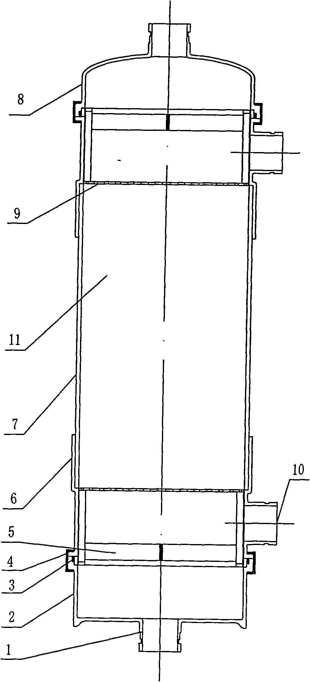
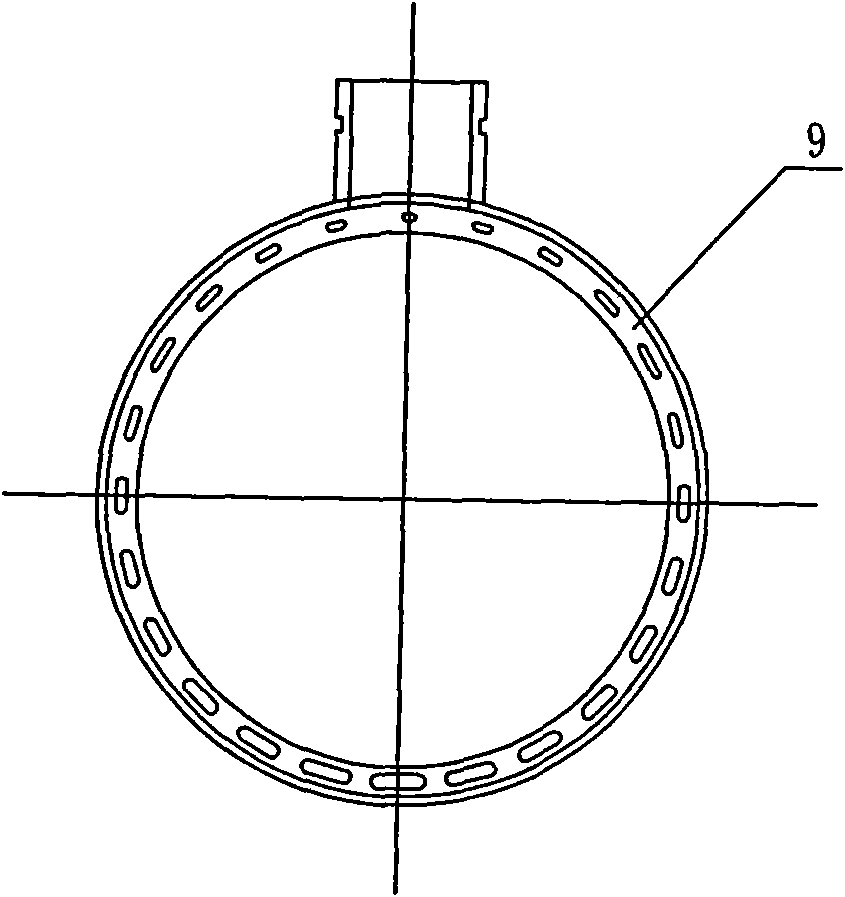
[0016] Such as figure 1 As shown, the upper and lower ends of the membrane main body 7 of the present invention are covered with an outer cylinder 6, and the interior of the membrane main body 7 is provided with a hollow fiber 11. The upper end of the hollow fiber 11 is provided with a water distributor 9, and the lower end is provided with a membrane lattice support. piece 5. Such as figure 2 As shown, the aperture of the water distribution hole of the water distributor 9 of the present invention gradually becomes larger as the distance from the water inlet 10 increases, and they are arranged in a ring shape. The size of the openings is based on the principle that the section of the water distribution hole is proportional to the water inlet flow path. The holes near the water inlet are small and few, and the holes far away from the water inlet are many and large. The i...


PUM


Abstract

The invention discloses a hollow fiber ultrafiltration membrane filter device which is characterized in that the hollow fiber ultrafiltration membrane filter device comprises a main body (7) of a membrane part, outer cylinders (6) are sheathed at the upper end and the lower end of the main body (7) of the membrane part, a hollow fiber (11) is arranged in the main body (7) of the membrane part, a water distributor (9) is arranged at the upper end of the hollow fiber (11), a membrane sub-grid supporting part (5) is arranged at the lower end, pore diameters of water distribution holes of the water distributor (9) are gradually increased along with the increase of the distance to a water inlet (10), the water distribution holes are annularly arranged, the upper part of the outer cylinder (6) at the upper end of the main body (7) of the membrane part is connected with an upper terminal (8), the lower part of the outer cylinder (6) at the lower end of the main body (7) of the membrane part is connected with a lower terminal (2), and a port (1) is formed at the lower end of the lower terminal (2). The hollow fiber ultrafiltration membrane filter device has the advantages of beautiful appearance, convenient manufacture and assembly, large flux, good sealing performance and small occupied space, thereby being particularly applicable to industrial water purification.

Description

technical field [0001] The invention relates to an ultrafiltration device in the field of water treatment, in particular to a hollow fiber ultrafiltration membrane filtration device. Background technique [0002] At present, the ultrafiltration membrane modules used in the field of water treatment generally use plexiglass tubes for their membrane shells, which are easily broken, and the resin is not evenly distributed during casting, making installation difficult and low flux. Some ultrafiltration membrane modules use UPVC tubes for their membrane shells and ABS engineering plastics for their outer cylinders. When two different materials are cemented together, they are prone to poor bonding, which leads to water leakage, and the tensile strength and toughness of UPVC tubes are relatively low. Poor, often manifested as brittleness, low elongation and easy fracture. When the sealing structure is connected to the outside, it is generally threaded or directly pressed with a gas...

Claims


Application Information

Patent Timeline
Patent Type & Authority Applications(China)
IPC IPC(8): B01D61/18B01D63/02C02F1/44
CPCC02F1/006B01D2313/10B01D2313/12B01D61/18B01D61/145C02F1/444B01D63/02
Inventor 钱盘生刘立忠
Owner JIANGSU JINSHAN ENVIRONMENTAL PROTECTION TECH
Why Eureka
Try Eureka