Release packer capable of well-flushing

A packer and well flushing technology, applied in the directions of sealing/packing, cleaning equipment, wellbore/well components, etc., can solve the problems of the packer being unable to be seated, the construction success rate is low, and it cannot be completed, etc., to achieve reliable Seat seal, the effect of significant economic benefits

Active Publication Date: 2010-06-16
DONGYING BAIHUA GASOLINEEUM TECH DEV
View PDF0 Cites 20 Cited by
  • Summary
  • Abstract
  • Description
  • Claims
  • Application Information

AI Technical Summary

Problems solved by technology

Packers are used for layered water plugging. There are many types of existing packers, but there are problems such as easy failure, slippage, low bearing capacity, low construction success rate, and difficulty in unsealing.
There is a type of packer on site that is brought to the oil layer by the tubing to press the seat seal, and then the tubing and the packer are separated. This process is called dropping hands on site. To meet the requirements of the hydraulic seat seal, it and its lower pipe string are airtight, the internal liquid cannot come out, and the external liquid cannot enter. Therefore, the pipe string cannot be cleaned after the completion of the well, resulting in the inside of the pipe string. The channel is blocked by debris, so that the pressure cannot be transmitted to the piston, and the required action cannot be completed, the packer cannot be set and sealed, and the purpose of layered oil recovery cannot be realized

Method used


Image

  • Release packer capable of well-flushing
  • Release packer capable of well-flushing
  • Release packer capable of well-flushing

Examples


Embodiment Construction

[0008] Embodiments of the present invention will be described below in conjunction with the accompanying drawings.

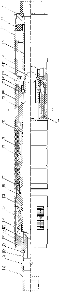
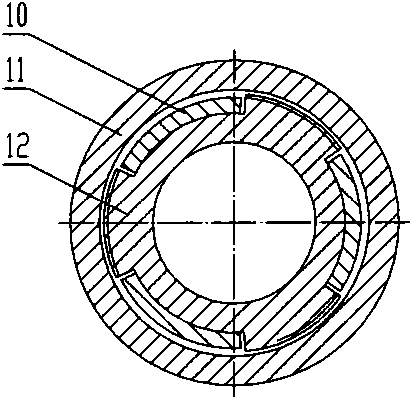
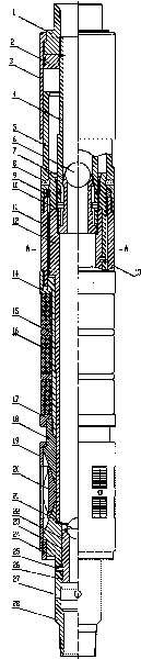
[0009] The embodiment of the present invention consists of an upper joint 1, a piston 2, a hydraulic cylinder 3, a separation joint 4, a push tube 5, a seat seal valve ball 6, a seat seal valve seat 7, a seat seal shear nail 8, a lock ring 9, and a fishing joint 10 , connecting pipe 11, inner pipe 12, unsealing shear nail 13, upper rubber sleeve joint 14, rubber sleeve shaft 15, rubber sleeve 16, lower rubber sleeve joint 17, upper cone 18, slip sleeve 19, slip 20, Closing valve ball 21, upper sealing ring 22, stop joint 24, pin 25, lower sealing ring 26, lower cone 28, upper joint 1 lower external thread is connected with hydraulic cylinder 3 upper part, upper joint 1 lower internal thread and separation joint 4. The upper part is connected. The piston 2 is installed between the hydraulic cylinder 3 and the separation joint 4. Below the piston 2 is a push tube ...


PUM


Abstract

The invention discloses a release packer capable of well-flushing, which comprises an upper joint, a piston, a hydraulic cylinder, a separating joint, an ejector sleeve, a packing valve ball, a packing valve seat, a packing shear pin, a lock ring, a junk sub, a connected pipe, an inner pipe, an unset shear pin, an upper rubber cylinder joint, a rubber cylinder shaft, a rubber cylinder, a lower rubber cylinder joint, an upper cone, a slip sleeve, a slip, a lower cone, and a stop joint; wherein the lower cone is provided with a communicated hole and internally provided with a sliding sleeve; the sliding sleeve is positioned above the communicated hole and fixed on the lower cone; the upper part of the sliding sleeve is provided with an upper seal ring, and the lower part of the sliding sleeve is provided with a lower seal ring; a pin is positioned between the upper seal ring and the lower seal ring; a cut-off valve ball is located in the upper port of the sliding sleeve; and the diameter of the cut-off valve ball is smaller than the inner diameter of the packing valve seat. Before packing, the reverse well flushing can be carried out on an oil pipe on the packer so as to wash way sundries in the oil pipe and ensure that a packing pressure is transferred to the piston, the packer can be reliably packed and the well flushing can successfully realize oil production by layer, thereby the invention has obvious economic benefit.

Description

technical field [0001] The invention relates to a downhole layered oil recovery tool for oil recovery in an oil field, in particular to a packer capable of washing wells. Background technique [0002] It is an effective way to control the rise of water cut in oil wells by implementing layered blocking water recovery technology to seal off high aquifers. Packers are used for layered water plugging. There are many types of packers, but there are problems such as easy failure, slippage, low bearing capacity, low construction success rate, and difficulty in unsealing. There is a type of packer on site that is brought to the oil layer by the tubing to press the seat seal, and then the tubing and the packer are separated. This process is called dropping hands on site. To meet the requirements of the hydraulic seat seal, it and its lower pipe string are airtight, the internal liquid cannot come out, and the external liquid cannot enter. Therefore, the pipe string cannot be cleaned...

Claims


Application Information

Patent Timeline
Patent Type & Authority Applications(China)
IPC IPC(8): E21B33/129E21B37/00E21B43/00
Inventor 周娜张韬王军刘嘉九薜涛
Owner DONGYING BAIHUA GASOLINEEUM TECH DEV
Why Eureka
Try Eureka