Bearing cage

A technology of bearing retainer and retainer, which is applied in the direction of bearing components, shafts and bearings, mechanical equipment, etc., can solve the problems of troublesome use and difficult grinding process in the later stage, and achieve the effects of convenient and simple processing, simplified process and improved production efficiency

Inactive Publication Date: 2010-06-23
潘冬东
View PDF1 Cites 3 Cited by
  • Summary
  • Abstract
  • Description
  • Claims
  • Application Information

AI Technical Summary

Problems solved by technology

Since the bearing retainer is a closed structure, it is very difficult to grind the cavity on the bearing retainer during the production process; and it is also troublesome to use later

Method used


Image

  • Bearing cage
  • Bearing cage
  • Bearing cage

Examples


Embodiment Construction

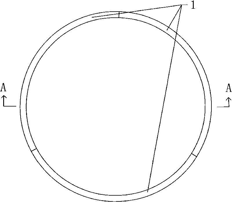
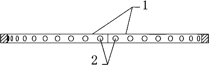
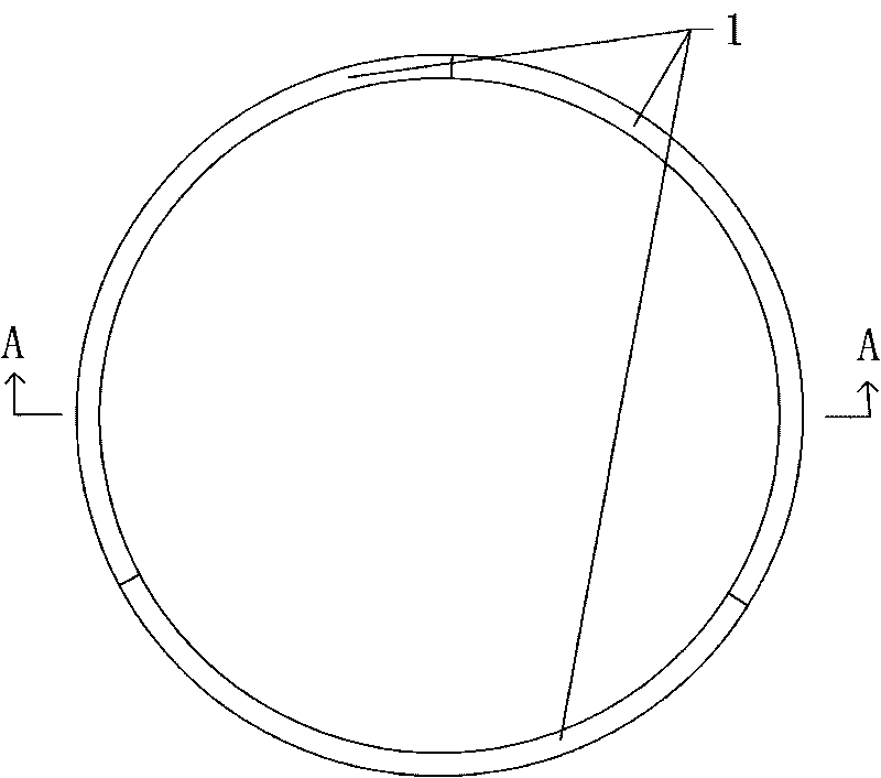
[0011] Such as figure 1 , 2 As shown, the bearing retainer is ring-shaped and consists of three arc-shaped retaining pieces 1 with the same shape and size. The radian of the holding piece 1 is 120 degrees, so that the three sections of holding piece 1 form a complete circle. A plurality of window holes 2 are provided on the concave side of each holding piece 1, and the window holes 2 are used to fix various supports, such as balls and rollers. In order to make the supports fixed on the bearing holder evenly distributed, the window holes 2 on each section of the holding piece 1 are evenly distributed, and the distance from the window hole 2 at any end of the holding piece 1 to the corresponding end of the holding piece 1 is adjacent. 1 / 2 of the distance between the window holes 2, which ensures that the distance between the window holes 2 at the adjacent ends of the two sections of the retaining sheet 1 is the same as the whole.


PUM


Abstract

The invention discloses a bearing cage, which at least comprises three arc retaining sheets. The inside of each retaining sheet is provided with a window opening. A plurality of retaining sheets are connected end to end to form the bearing cage, thus, only the operation of processing the retaining sheets needs to be carried out in the production process, and the retaining sheets have simple and convenient processing so as to simplify the production process of the bearing cage and greatly improve the production efficiency. The bearing cage is of a separated structure so as to have very convenient use.

Description

technical field [0001] The invention relates to a bearing retainer Background technique [0002] Existing bearing retainers are all ring-shaped. For example, in the Chinese patent disclosed on May 26, 2004, the publication number is CN1499095A, which discloses a retainer for retaining the support in the bearing. C-shaped pocket for holding the support. Between the pockets is a connecting portion, which is closer to the pocket opening. The back of the adjacent two pockets and the back of the connecting portion for the adjacent pockets form a recess dug deeply into the holder, the bottom of which is larger than the bottom of the pocket. closer to the opening this. Since the entire bearing retainer has a closed structure, it is very difficult to grind the recesses on the bearing retainer during the production process; moreover, it is troublesome to use later. Contents of the invention [0003] The technical problem to be solved by the present invention is to provide a bea...

Claims


Application Information

Patent Timeline
Patent Type & Authority Applications(China)
IPC IPC(8): F16C33/38
Inventor 潘冬东
Owner 潘冬东
Why Eureka
Try Eureka