Liquid crystal display, active matrix substrate, liquid crystal panel, liquid crystal display unit, and television receiver

A liquid crystal display device and potential technology, which can be used in TVs, color TVs, components of color TVs, etc., and can solve problems such as limited effects.

Inactive Publication Date: 2010-11-03
SHARP KK
View PDF7 Cites 7 Cited by
  • Summary
  • Abstract
  • Description
  • Claims
  • Application Information

AI Technical Summary

Problems solved by technology

[0006] The above pixel segmentation method improves the viewing angle dependence of the γ characteristic of the pixel unit by superimposing the γ characteristic of each sub-pixel, but the above-mentioned effect of the existing structure of forming two sub-pixels in one pixel is limited

Method used


Image

  • Liquid crystal display, active matrix substrate, liquid crystal panel, liquid crystal display unit, and television receiver
  • Liquid crystal display, active matrix substrate, liquid crystal panel, liquid crystal display unit, and television receiver
  • Liquid crystal display, active matrix substrate, liquid crystal panel, liquid crystal display unit, and television receiver

Examples


Embodiment approach 1

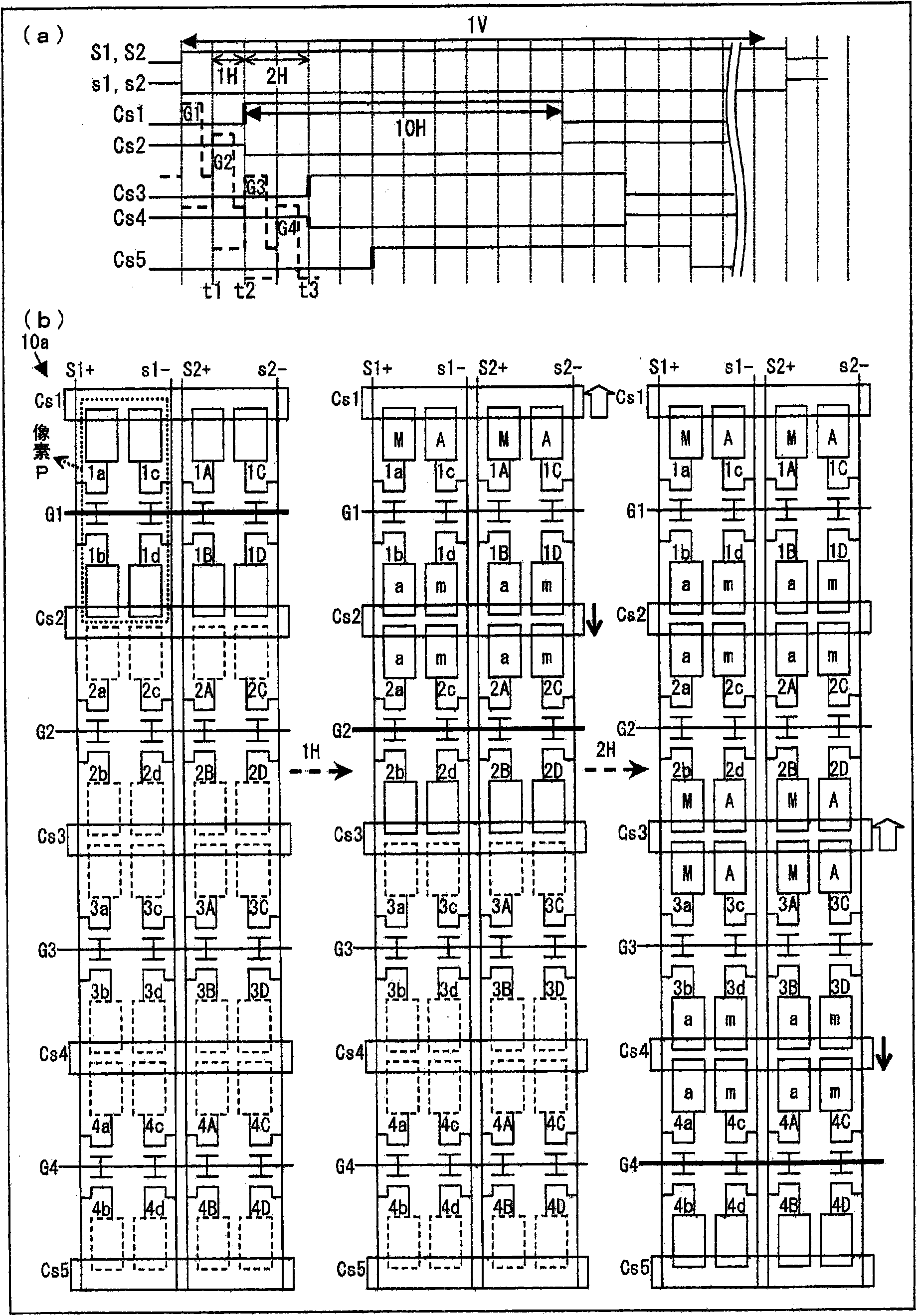
[0096] Below, explain figure 1 The way. figure 1 (a) is a timing chart showing a method of driving a display portion of the liquid crystal display device, figure 1 (b) is a schematic diagram illustrating the structure of the display unit and its driving process. figure 1 The left figure of (b) shows figure 1 The state of t1 in (a), the middle figure shows figure 1 The state of t2 in (a), the right figure shows figure 1 (a) The state of t3. Such as figure 1 As shown in (b), in the display portion 10a, corresponding to one pixel column, first and second data signal lines are provided on both sides thereof, and four sub-pixels connected to the same scanning signal line are provided in one pixel. The pixel corresponds to two storage capacitor wirings, the two sub-pixels of the pixel form a capacitor with one of the two storage capacitor wirings, and one of the two sub-pixels is connected to the first data signal line, and the other is connected to the first data sign...

Embodiment approach 2

[0166] Below, explain Figure 26 The way. Figure 26 (a) is a timing chart showing a method of driving a display portion of the liquid crystal display device, Figure 26 (b) is a schematic diagram illustrating the structure of the display unit and its driving process. Figure 26 The left figure of (b) shows Figure 26 The state of t1 in (a), the middle figure shows Figure 26 The state of t2 in (a), the right figure shows Figure 26 (a) The state of t3. Such as Figure 26 As shown in (b), in the display portion 10b, corresponding to one pixel column, first and second data signal lines are provided on both sides thereof, and one pixel is provided with three sub-pixels connected to the same scanning signal line. The pixel corresponds to two storage capacitor wirings, the two sub-pixels of the pixel form a capacitor with one of the two storage capacitor wirings, and one of the two sub-pixels is connected to the first data signal line, and the other is connected to the first...


PUM

PropertyMeasurementUnit
greyscaleaaaaaaaaaa

Abstract

First and second data signal lines (S1, s1) are provided correspondingly to one row of pixels, four sub-pixels (1a to 1d) connected to the same scanning signal line (e.g., G1) are included in a pixel (P) to which two storage capacitor lines (Cs1, Cs2) correspond. Two sub-pixels (1a, 1c) of the pixel (P) form the capacitor with one (Cs1) of the two storage capacitor lines. One (1a) of the sub-pixels is connected to the first data signal line (S1) and the other (1c) is connected to the second data signal line (s1). The remaining two sub-pixels (1b, 1d) form the capacitor with the other (Cs2) of the two storage capacitor lines. One (1b) of the sub-pixels is connected to the first data signal line (S1) and the other (1d) is connected to the second data signal line (s1). With the configuration, the four sub-pixels arranged in one pixel are controlled to different luminance levels to allow gradation display.

Description

technical field [0001] The present invention relates to a liquid crystal display device of a pixel division method in which one pixel is constituted by a plurality of sub-pixels, and an active matrix substrate and a liquid crystal panel used in the liquid crystal display device. Background technique [0002] As one method for improving the viewing angle dependence of the γ characteristic of the liquid crystal display device (the difference between the γ characteristic when the liquid crystal display device is viewed from the front and the γ characteristic when the liquid crystal display device is viewed obliquely), it has been proposed to use a plurality of sub-pixels A method of dividing pixels into one pixel (so-called multi-pixel technique) (for example, refer to Patent Document 1). [0003] Figure 46 An equivalent circuit of a liquid crystal display device of a pixel division method is shown. As shown in the figure, this liquid crystal display device is provided with o...

Claims


Application Information

Patent Timeline
Patent Type & Authority Applications(China)
IPC IPC(8): G02F1/1368G02F1/133G09G3/20G09G3/36H04N5/66
CPCG02F2001/134345G09G3/2074G02F1/136213G09G2320/028G02F1/136286G02F1/13624G09G3/3607G09G2300/0447G09G3/3648G09G2300/0876G09G2300/0426G02F1/134345
Inventor 津幡俊英
Owner SHARP KK
Why Eureka
Try Eureka