System for detecting connectivity of bank cable and method thereof

A multi-core cable and detection method technology, which is applied in the field of communication transmission system, can solve problems such as error-prone, cable core disconnection, cumbersome wiring replacement, etc., and achieve the effects of improving work efficiency, ensuring accuracy, and strong scalability

Active Publication Date: 2011-01-05
INST OF ACOUSTICS CHINESE ACAD OF SCI
View PDF6 Cites 26 Cited by
  • Summary
  • Abstract
  • Description
  • Claims
  • Application Information

AI Technical Summary

Problems solved by technology

In practical applications, multi-core cables often have connectivity faults such as cable core disconnection, short circuit, and wrong connection. There are various inconveniences in its detection and identification
[0004] In engineering applications, it is generally identified by the position of each core wire and different color codes, but this method is prone to errors when the number of core wires is relatively large
There is another method that is more commonly used, that is, connect the two ends of the cable core wire to the telephone respectively, and conduct the test through the conversation of the staff at both ends. The disadvantage of this method is that the efficiency is very low, and at least two people are required to operate at the same time.
When one party is operating, he must try the core wires one by one until he finds the one that both parties can talk to. At this time, the other party will change another core wire, and the first party will try to talk again, so this method is the best. It is best to do it when both parties can hear each other's speech. Due to the cumbersome wiring, easy to make mistakes, heavy manual labor and too harsh application conditions, it cannot be popularized.

Method used


Image

  • System for detecting connectivity of bank cable and method thereof
  • System for detecting connectivity of bank cable and method thereof
  • System for detecting connectivity of bank cable and method thereof

Examples


Embodiment Construction

[0043] A system and method for detecting the connectivity performance of multi-core cables proposed by the present invention will be further described below in conjunction with the accompanying drawings and embodiments.

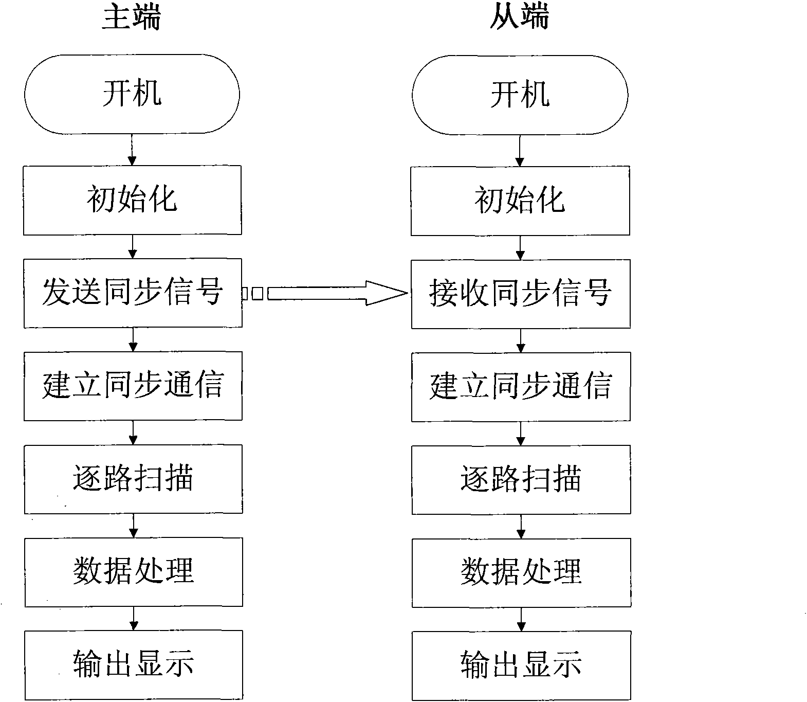
[0044] A kind of test process block diagram of multi-core cable connectivity performance detection method that the present invention proposes, as figure 2 As shown, the specific test steps are as follows:

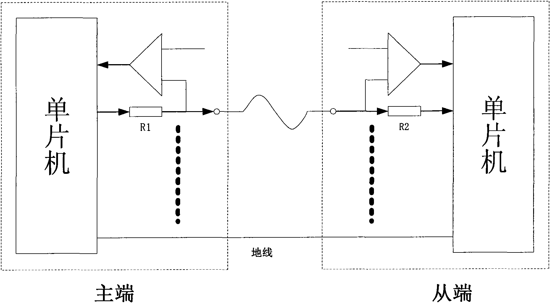
[0045] Step 1), the master and slave microcontrollers start to initialize respectively, and the slave microcontrollers enter the scanning state immediately, waiting for the synchronization signal sent by the master microcontroller;

[0046] Step 2), the master-side single-chip microcomputer sends a synchronization signal to the slave-side single-chip microcomputer to establish communication;

[0047] Step 3), after the communication is established, under the control of the master-side single-chip microcomputer, the 24-way core circuits output high levels...


PUM


Abstract

The invention relates to a system for detecting the connectivity of a bank cable and a method thereof. In the system, a primary test end carries out detection through a tested cable together with a secondary test end; the primary test end and the secondary test end respectively comprises a voltage comparator, a test resistor and a singlechip; the singlechip at the primary end is connected to one end of one core wire of the cable through the test resistor, and the other end of the core wire is connected to the singlechip of the secondary end through the test resistor; the ends which are connected with the core wire of the cable, of the test resistances of the primary end and the secondary end are respectively connected with one voltage comparator; the output end of each voltage comparator is connected to the singlechip; when in test, the singlechip at the primary end respectively outputs high level to one core wire of the tested cable and low level to the other core wires of the tested cable, the current passes through the tested resistance, the voltage comparator of each core wire compares the detected voltage value with the reference voltage to obtain a logical result, the logical result is respectively input to the singlechips at the primary end and the secondary end and is comprehensively analyzed so as to judge whether each core wire is in a normal state, a disconnection state, a misconnection state, a state of short-circuit with the ground or a state of short-circuit between conductors.

Description

technical field [0001] The invention relates to transmission media in the field of communication transmission systems, in particular to a system and method for detecting the connectivity performance of multi-core cables. Background technique [0002] With the rapid development of the communication industry in the past two decades, communication cables have been widely used in information transmission systems, and cables are playing an increasingly important role in national economic construction. In daily life, the application of cables is everywhere. The length of cable laying is also getting longer and longer. As early as the middle of the 20th century, the first submarine cable of mankind was successfully laid. In the construction of various projects now, it is inseparable from the laying of cables everywhere. At the same time, how to correctly identify them in engineering construction has become a new problem. [0003] In experimental work and engineering construction...

Claims


Application Information

Patent Timeline
Patent Type & Authority Applications(China)
IPC IPC(8): G01R31/02G01R31/08H04B3/46
Inventor 程晓斌阎兆立陈杰
Owner INST OF ACOUSTICS CHINESE ACAD OF SCI
Why Eureka
Try Eureka