Sewage aerobic land treatment system

A technology for land treatment and sewage, applied in aerobic process treatment, energy and wastewater treatment, sustainable biological treatment, etc. High air transfer efficiency, improved backwashing effect, and stable treatment effect

Active Publication Date: 2011-04-06
QINGDAO LIGONG NEW ENVIRONMENTAL TECH DEV
View PDF4 Cites 14 Cited by
  • Summary
  • Abstract
  • Description
  • Claims
  • Application Information

AI Technical Summary

Problems solved by technology

[0004] However, the disadvantages of the traditional sewage land treatment system are that it occupies a relatively large area, is greatly affected by the climate, has poor operation effect in winter, breeds mosquitoes and flies in summer, and has a certain smell. The treatment efficiency gradually decreases, the system is prone to blockage and adsorption saturation, only anaerobic section, poor nitrogen and phosphorus removal effect, etc.
The system adopts wind energy exhaust fan to naturally ventilate the treatment system, which does not consume electric energy and solves the problem of oxygen supply, but there are the following defects: 1. Using natural ventilation, the aeration volume cannot be adjusted according to the quality and quantity of influent water; 2. Polymer hydrophobic It is difficult to replace the damaged air-permeable membrane, and the cost is high; 3. Natural ventilation is adopted, the wind pressure is small, the mass transfer efficiency from air to soil is relatively low, and the reoxygenation effect is poor
This method adopts air reoxygenation, which has the same defects as the Chinese patent with application number 200410017544.5: the air pressure is small, the mass transfer efficiency from air to soil is relatively low, the reoxygenation effect is poor, and it is difficult to control the operating conditions. Nitrogen and phosphorus removal effect is poor

Method used


Image

  • Sewage aerobic land treatment system
  • Sewage aerobic land treatment system
  • Sewage aerobic land treatment system

Examples


Embodiment Construction

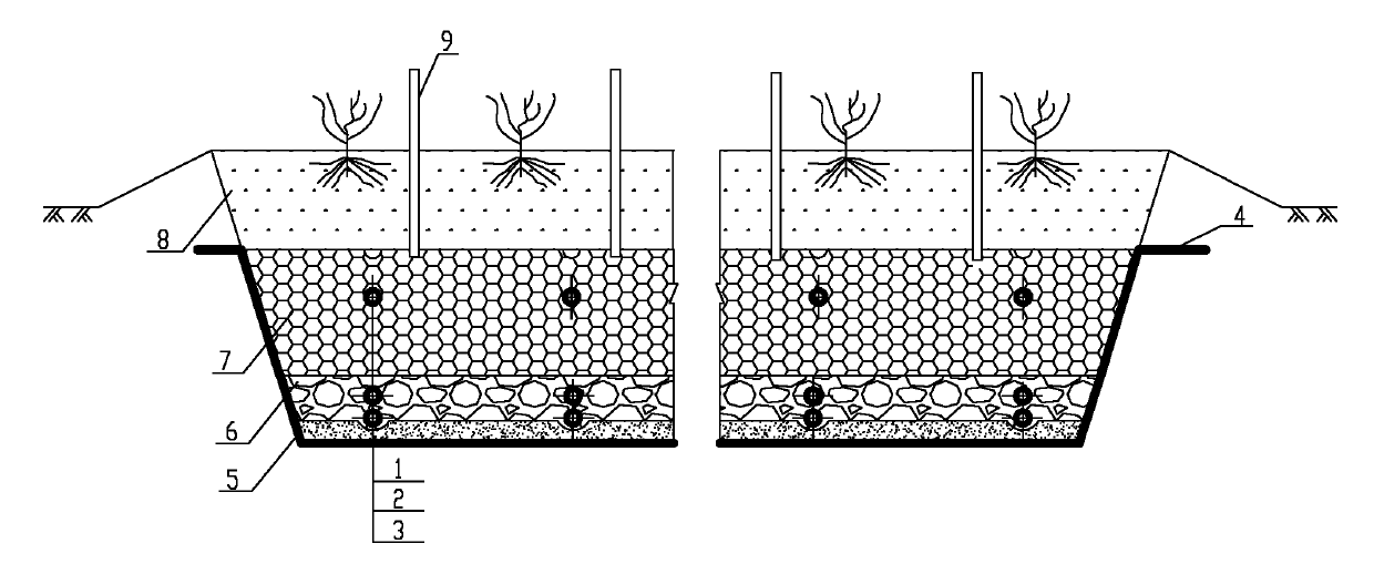
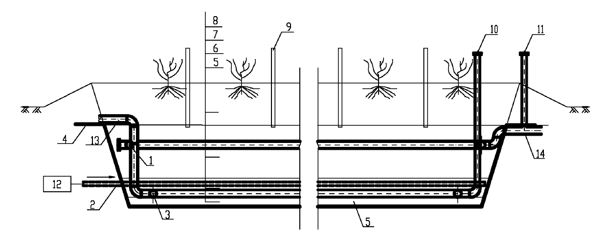
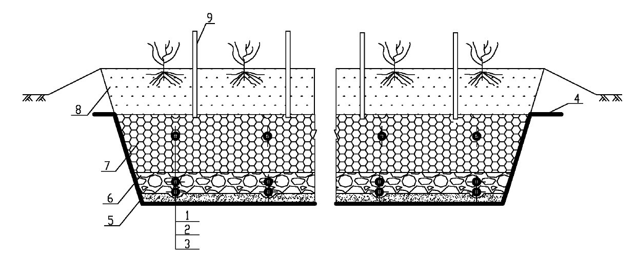
[0022] The present invention will be further described below in conjunction with the accompanying drawings and through specific embodiments.

[0023] Such as figure 1 and figure 2 As shown, the present invention comprises a trapezoidal trough, which is excavated below the ground, and is covered with an anti-seepage film 4 around and at the bottom. It is filled with three parts, from bottom to top are sand layer 5, water distribution layer 6, filler and water collection layer 7, soil layer 8, and water distribution pipe 3, aeration pipe 2 and filler laid in water distribution layer 5 With the water collecting pipe 1 and the air outlet pipe 9 in the water collecting layer 7. A plurality of holes are arranged on the pipe walls of the water distribution pipe 3 and the water collection pipe 1 . Wherein, the water distribution pipe 3 is close to the bottom, covered with pebbles, and the water collection pipe 1 is near the soil layer 8 on the top of the filler and the water colle...


PUM

PropertyMeasurementUnit
porosityaaaaaaaaaa

Abstract

The invention discloses a sewage aerobic land treatment system. The system comprises a groove body formed by digging under the ground, wherein impermeable membranes are laid at the periphery and at the bottom of the groove body; and a sand layer, a water distribution layer, a packing and water collecting layer and a soil layer are formed in turn from bottom to top. The sewage aerobic land treatment system is characterized by also comprising a blast aeration system consisting of a blast blower, an air diffusion device and a connecting pipeline, wherein the air diffusion device is positioned below the water surface of the land treatment system and connected with the blast blower through a pipeline; pretreated sewage enters the land treatment system; and air is pressurized by the blast blower and diffused into sewage of the system in the form of small air bubbles through the air diffusion device. Therefore, the aims of charging oxygen into the sewage and stirring are fulfilled, good reoxygenation effect, high mass transfer efficiency, quick bio-membrane updating and high treatment efficiency are achieved, and the problem of blockage of the land treatment system in the operating process is solved effectively.

Description

technical field [0001] The invention relates to an aerobic land treatment system for treating sewage by artificial aeration, and belongs to the technical field of sewage ecological treatment. Background technique [0002] Due to the lack of reasonable feces collection measures in rural areas, the relevant domestic sewage and the feces, waste water, animal blood, egg shells and other pollutants produced by the livestock and poultry breeding industry cannot be effectively treated. In addition, some small towns, parks, seaside tourist destinations, newly developed residential areas, hotels and restaurants, etc. do not have the conditions to set up sewage treatment stations, so more than 90% of the sewage in these areas is directly discharged into nearby oceans and rivers without treatment. , In lakes, the water source and the environment are polluted, resulting in excessive N and P in the water body, serious eutrophication, and even blackening of the water body. [0003] Howev...

Claims


Application Information

Patent Timeline
Patent Type & Authority Applications(China)
IPC IPC(8): C02F3/02
CPCY02W10/10Y02W10/33
Inventor 王森贾卫利王萍郭一令
Owner QINGDAO LIGONG NEW ENVIRONMENTAL TECH DEV
Why Eureka
Try Eureka