Optical fiber bundle fluorescent sensor

A fluorescent sensor and sensor technology, which is applied in the direction of fluorescence/phosphorescence, material excitation analysis, etc., can solve the problems of increasing light source interference and energy consumption, and achieve the effects of improving receiving efficiency, improving sensitivity, and strong practicability

Inactive Publication Date: 2011-06-22
DALIAN INST OF CHEM PHYSICS CHINESE ACAD OF SCI
View PDF0 Cites 20 Cited by
  • Summary
  • Abstract
  • Description
  • Claims
  • Application Information

AI Technical Summary

Problems solved by technology

The enhancement of the light source intensity can indeed increase the fluorescence intensity to a certain extent, but it also increases the interference of the light source to the detection and the increase of energy consumption

Method used


Image

  • Optical fiber bundle fluorescent sensor
  • Optical fiber bundle fluorescent sensor

Examples


Embodiment 1

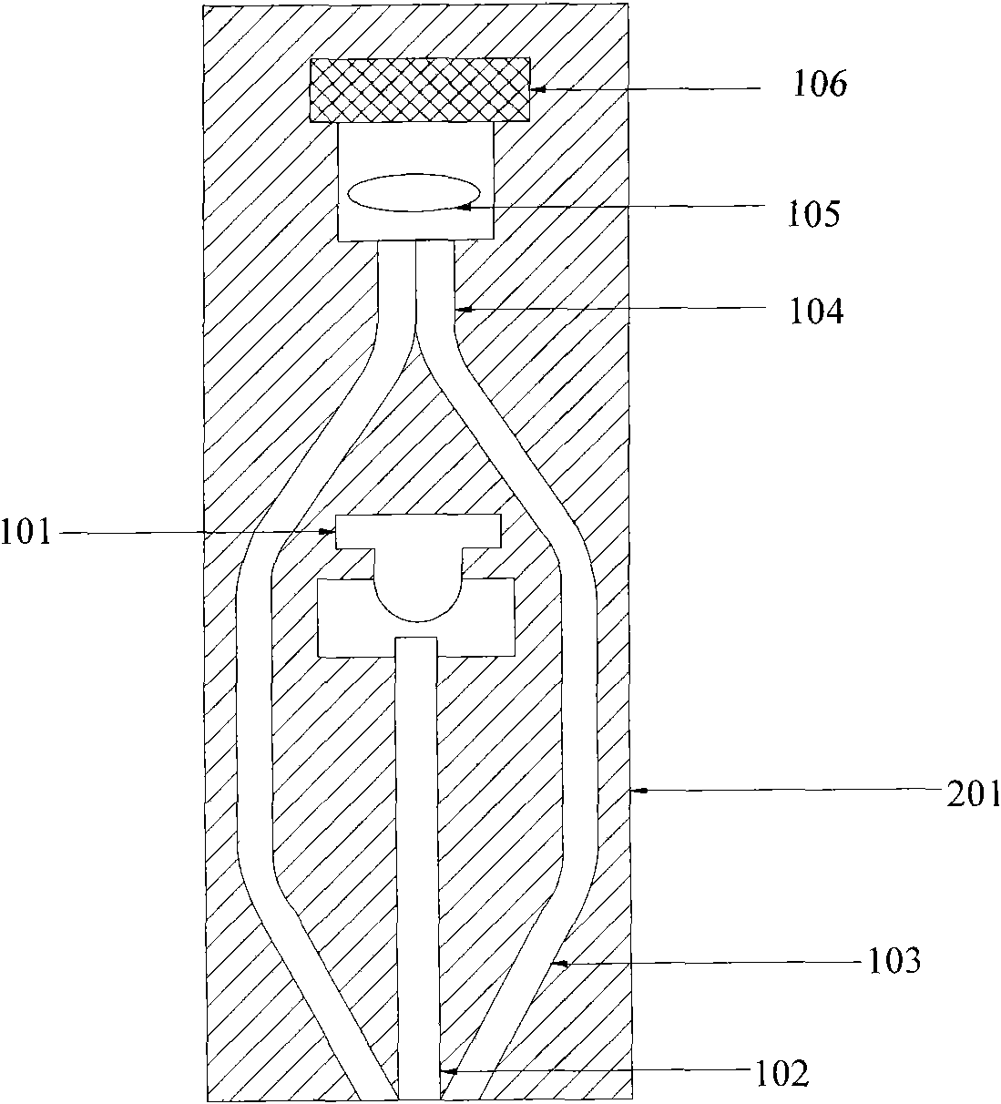
[0026] like figure 1 As shown, a fluorescent optical fiber sensor for directly detecting fluorescent substances, its structure includes an excitation light source 101 (high-power light-emitting diode), an excitation optical fiber 102, and a bundled receiving optical fiber 103 composed of three single optical fibers. The optical path of the excitation light source 101 Coupled with the incident end of the exciting optical fiber 102, the outgoing ends of the three receiving optical fibers 103 are attached in parallel, and their end faces are on the same plane, and the end faces form a merged end 104. 105 is coupled with a photoelectric conversion device 106 (silicon photocell); the outgoing end of the exciting fiber 102 and the incident end of the receiving optical fiber 103 are in the same plane, and the outgoing end of the exciting optical fiber 102 is the axis of symmetry, and the incident ends of the three receiving optical fibers 103 are in the same plane. Axisymmetric unifo...

Embodiment 2

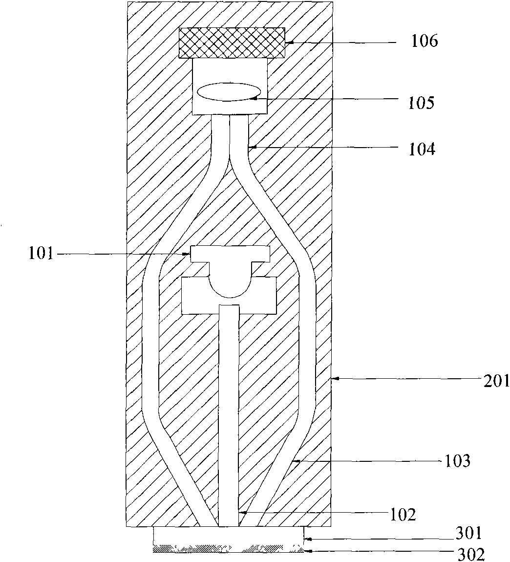
[0035] like figure 2 As shown, a fluorescent fiber optic sensor for indirect detection of non-fluorescent substances,

[0036] The difference from Embodiment 1 is that there are four receiving optical fibers 103;

[0037] Taking the exit end of the exciting fiber 102 as the axis, the incident end of the receiving optical fiber 103 is evenly arranged around, and the receiving optical fiber 103 is evenly arranged around the exciting optical fiber 102,

[0038] A transparent carrier sheet 301 is provided outside the incident end of the receiving optical fiber 103 and the outgoing end of the exciting optical fiber 102 , and a sensing film 302 embedded with fluorescent probes is coated on the lower surface of the transparent carrier sheet 301 . A filter 105 is arranged between the combined end 104 of the bundled receiving fiber end face and the photoelectric conversion device 106 .

[0039] The excitation light source 101 of the optical fiber sensor, the excitation optical fiber...


PUM


Abstract

The invention relates to an optical fiber bundle fluorescent sensor. The system adopts a light-emitting diode as an excitation light source, a single optical fiber is taken as an excitation optical fiber to transmit an exciting light, multiple optical fibers are surrounded at the periphery of the end face at the exit of a transmitting optical fiber to form an optical fiber bundle to receive a fluorescent light, and the fluorescent light is transmitted to a merge end and then is transmitted to a photoelectric converter by virtue of a light filter to be detected, wherein the single optical fibers in the optical fiber bundle are uniformly arranged at the periphery of the excitation optical fiber in a certain included angle. The sensor is simple in structure, is convenient to use and has low cost, and the fluorescent light can be efficiently received and the signal to noise ratio and the detection sensitivity can be improved by optimizing the included angle between the transmitting optical fiber and a receiving optical fiber. The sensor can be applicable to direct detection on gas and liquid non-solid state fluorescent substances and detection on non-fluorescent substances by combining with a fluorescent sensing membrane.

Description

technical field [0001] The invention relates to a light-emitting diode-induced fluorescent optical fiber sensor, in particular to an optical fiber sensor which can directly detect non-solid fluorescent substances such as gas and liquid, and can also be combined with a fluorescent sensing film to indirectly detect non-fluorescent substances. Background technique [0002] As a photoluminescent detection technology, fluorescence detection has the advantages of high sensitivity and strong selectivity, and is widely used in the detection of trace samples. The fluorescent optical fiber sensor uses optical fiber as the transmission means to transmit the fluorescent signal. It not only has the characteristics of high sensitivity and strong selectivity of the fluorescence method, but also has strong anti-electromagnetic interference ability of the optical fiber, low transmission loss of the obtained optical information, and large transmission capacity. There is no need for a referenc...

Claims


Application Information

Patent Timeline
Patent Type & Authority Applications(China)
IPC IPC(8): G01N21/64
Inventor 熊艳关亚风王建伟刘静
Owner DALIAN INST OF CHEM PHYSICS CHINESE ACAD OF SCI
Why Eureka
Try Eureka