Magnetic coupling controlling means

A control device and magnetic coupling technology, which is applied in the direction of electromechanical devices, magnetic drive clutches, and single motor speed/torque control, can solve the problems of compact processing devices, reduced drive efficiency, and increased volume of magnetic motors, so as to increase the speed Accuracy, improved controllability, and the effect of preventing out-of-step

Inactive Publication Date: 2011-08-10
HITACHI CABLE
View PDF0 Cites 3 Cited by
  • Summary
  • Abstract
  • Description
  • Claims
  • Application Information

AI Technical Summary

Problems solved by technology

Therefore, in order to compensate for the decrease in drive efficiency due to the eddy current, it is necessary to increase the size of the magnetic motor, and there is a problem that it is difficult to make the processing device compact.

Method used


Image

  • Magnetic coupling controlling means
  • Magnetic coupling controlling means
  • Magnetic coupling controlling means

Examples


Embodiment Construction

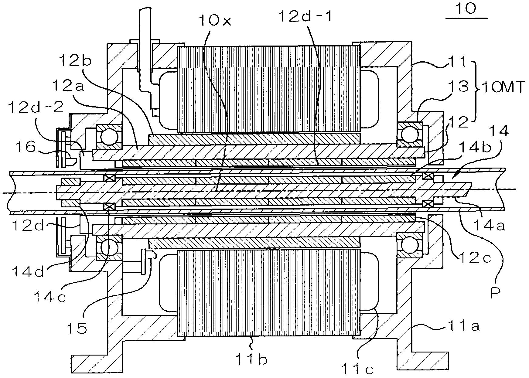
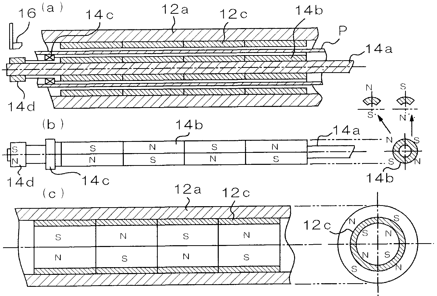
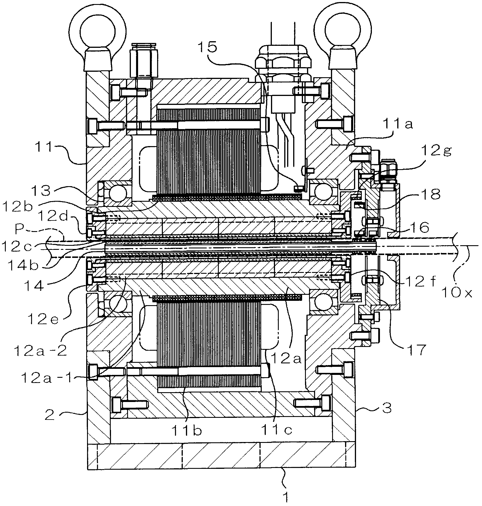
[0027] Next, embodiments of the magnetic coupling control device of the present invention will be described in detail with reference to the drawings. figure 1 It is a schematic longitudinal sectional view showing the basic structure of the embodiment, figure 2 It is partial figure (a)-(c) which shows each part of embodiment.

[0028] In the present embodiment, the magnetic coupling control device 10 includes an outer functional body 10MT having a stator portion 11 disposed on the outer periphery; and a rotor portion 12 disposed opposite to the inner side of the stator portion 11 . The outer functional body 10MT constitutes a DC brushless motor in the illustrated example. The stator unit 11 has a frame 11a opening (through) around the axis 10x and a plurality of stator poles 11b and coils 11c fixed inside the frame 11a and arranged around the axis 10x.

[0029] In addition, the rotor unit 12 has: a cylindrical magnetic cylinder (yoke) 12a rotatably supported by the frame 11a...


PUM


Abstract

A control mode is made into an easy adjustment corresponding to the load state or drive state of an inner side rotating body, and a better control mode is realized through an easy and compact structure. A magnetic coupling controlling means (10) comprises an outer side function body (10MT) of a rotor part (12) capable of rotating in an inner periphery, an inner side rotating body (14) which is disposed with intervals at the periphery side of the rotor part, tubings (P) of tube wall which are disposed between an external function body and an inner side rotating body, a magnetic coupling structure which is provided with a plurality of external side magnetic poles (12c) arranged around an axis in an inner periphery of the rotor part, and a plurality of internal side magnetic poles (14b) which match with the plurality of external side magnetic poles at the external periphery of the inner side rotating body and are arranged through magnetic coupling in a rotating direction, phase difference detection units (15, 16, 120) which detect the phase difference between the external side magnetic pole and the internal side magnetic pole, and external side function body control units (103, 106, 107) which control the external side function body based on the phase difference.

Description

technical field [0001] The present invention relates to a magnetic coupling control device, in particular to a device structure and control technology suitable for non-contact control of an inner rotating body arranged inside a pipe. Background technique [0002] Drive systems are known which use magnetic coupling for the transmission of rotational movements in a contactless manner. In this drive system using magnetic coupling, for example, it is known that a pair of magnetic disks having a plurality of magnetic poles arranged in a rotational direction are arranged at opposite positions, and in a manner synchronized with the rotation of one magnetic disk, it is possible to The structure that drives the other disk in rotation. [0003] On the other hand, in order to drive objects arranged in various pipes, there is also known a mechanism that uses magnetic force to drive the objects from the outside of the pipes. As piping, for example, besides a water pipe, a sewer pipe, e...

Claims


Application Information

Patent Timeline
Patent Type & Authority Applications(China)
IPC IPC(8): H02P6/08H02P6/16H02K16/02
CPCF16D27/01F16D27/14H02K1/06H02P6/16
Inventor 北岛宽规川田博司远山晖
Owner HITACHI CABLE
Why Eureka
Try Eureka