Clothes hanger station arriving and leaving conveying system

A conveying system and in-and-out station technology, which is applied in the field of hanger in-out station conveying system, can solve the problems of weakening of the top pressure between the driving teeth and elastic parts, affecting the normal opening and closing of hook claws, and inconvenient chain plate production, so as to reduce production costs , Relatively low installation position requirements, simple structure effect

Active Publication Date: 2012-02-15
INA INTELLIGENT TECH (ZHEJIANG) CO LTD
View PDF7 Cites 19 Cited by
  • Summary
  • Abstract
  • Description
  • Claims
  • Application Information

AI Technical Summary

Problems solved by technology

The structure of this kind of chain plate is relatively complicated. The shrapnel set on the chain plate is not convenient for the production of the chain plate, and it is easy to break due to fatigue damage, so the chain plate needs to be replaced
The elastic parts installed on the existing conveyor chain require the driving teeth on the drive wheel to press against during the working process to realize the opening and closing of the claws, thus requiring a high installation position between the conveyor chain and the drive wheel. Moreover, after the conveyor chain has been working for a long time, it is easy to weaken the pressing effect between the driving tooth and the elastic part due to wear and tear, which will affect the normal opening and closing of the claws.

Method used


Image

  • Clothes hanger station arriving and leaving conveying system
  • Clothes hanger station arriving and leaving conveying system
  • Clothes hanger station arriving and leaving conveying system

Examples


Embodiment Construction

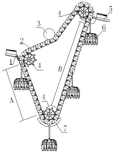
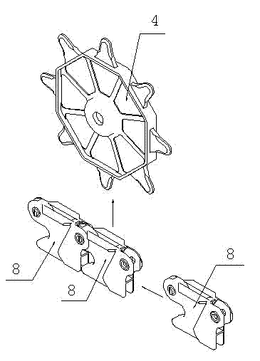
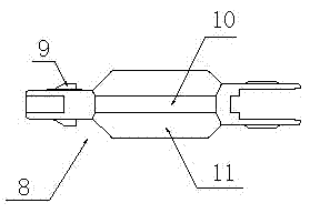
[0023] The main structure of the clothes hanger in and out station conveying system is a conveying chain 2, which is a closed ring and is composed of a plurality of chain plates 8 hinged head to tail in sequence. The head of the chain plate 8 is provided with a hook interface 12, thereby forming a hooking portion 13 connected with it on the chain plate 8, and the hinge points on the hooking portion 13 and the chain plate 8 are respectively located in the width direction of the chain plate 8. On the opposite sides, the hinge point on the chain plate 8 is biased towards the inner side of the conveyor chain 2 , and the hooking portion 13 is biased towards the outer side of the conveyor chain 2 . The two ends of the chain plate 8 in the length direction are respectively provided with a coupling head 9 and a coupling hole 16. The coupling head 9 and the coupling hole 16 are located on the same side in the width direction of the chain plate 8, that is, the coupling head 9 and the cou...


PUM


Abstract

The invention discloses a clothes hanger station arriving and leaving conveying system, and solves the problems that a conveying chain in the conventional flexible clothes hanger station arriving and leaving conveying system has a complex structure and is inconvenient to produce and assemble and low in using stability. The technical scheme is that: the clothes hanger station arriving and leaving conveying system comprises a station arriving guide rail, a station leaving guide rail, a conveying chain and a plurality of driving wheels, wherein the conveying chain is lapped with the driving wheels and comprises a plurality of chain plates. The system is characterized in that: the head of each chain plate is hinged with the tail of an adjacent chain plate; a hinge point of each chain plate inclines to the inner side of the conveying chain; the head of each chain plate is provided with a hook interface on the outer side of the hinge point on each chain plate; the conveying chain is provided with a descending part for driving a clothes hanger to descend and an ascending part for driving the clothes hanger to ascend; hook interfaces on the descending part and the ascending part on the conveying chain are in a closed state; hook interfaces on the conveying chain, which are positioned at the driving wheels, are in an open state; and the station arriving guide rail and the station leaving guide rail are close to one driving wheel respectively.

Description

technical field [0001] The invention relates to a conveying system for clothes hangers in and out of a station in a hanging system for clothes making, in particular to a conveying chain for conveying clothes hangers in and out of a work station. Background technique [0002] The requirement for garment production speed makes the garment hanging system widely used. The garment hanging system is equipped with multiple hangers for clamping different fabrics. The hangers run on the garment hanging system driven by the drive chain. In the system, several workstations are set along the direction of the drive chain, and a guide rail with a cylinder drive mechanism is set between each workstation and the drive chain for the hangers to enter and exit the workstation. Each workstation is equipped with a flexible conveyor chain or a belt-driven lifting arm with a fixed track, which is used to transport the completed hangers to the outbound mechanism. Compared with the belt-driven lifti...

Claims


Application Information

Patent Timeline
Patent Type & Authority Applications(China)
IPC IPC(8): B65G17/20B65G17/42B65G23/44
Inventor 翁端文
Owner INA INTELLIGENT TECH (ZHEJIANG) CO LTD
Why Eureka
Try Eureka