Seal valve with no-wear helical surface

A helical, wear-free technology, applied in valve details, valve device, valve housing structure, etc., can solve the problems of difficult manufacturing process, increase in the number of parts, increase manufacturing cost, etc., and achieve no friction torque and small opening and closing torque. , the effect of prolonging the service life

Inactive Publication Date: 2012-03-21
GUANGDONG PEARL FLUID MASCH CO LTD
View PDF6 Cites 1 Cited by
  • Summary
  • Abstract
  • Description
  • Claims
  • Application Information

AI Technical Summary

Problems solved by technology

However, these improvements have limitations. Although they have certain effects, they also bring new defects.
For example, compared with the original valve, the structure becomes more complex, the number of parts increases, the manufacturing process is difficult, the precision is high, and the manufacturing cost is increased.

Method used


Image

  • Seal valve with no-wear helical surface
  • Seal valve with no-wear helical surface
  • Seal valve with no-wear helical surface

Examples


Embodiment 1

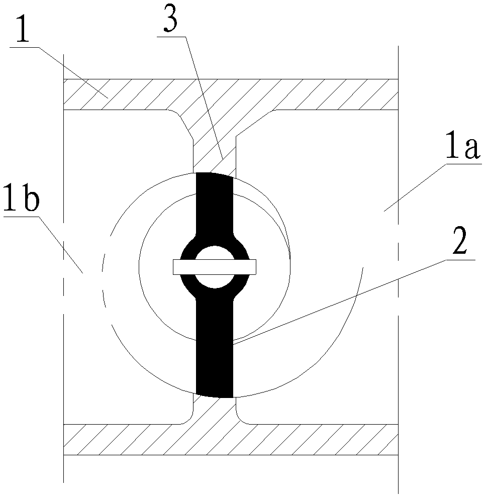
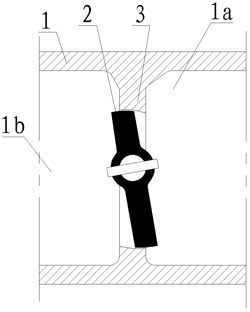
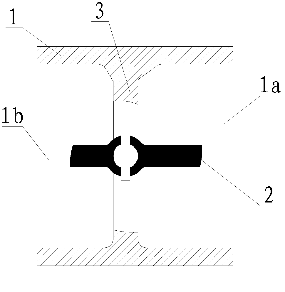
[0021] refer to Figure 1 to Figure 3 As shown, a wear-free helicoid sealing valve of the present invention includes a valve body 1, on which a medium inlet 1a and a medium outlet 1b are provided, and a valve core 2 and a valve seat 3 are arranged in the valve body 1, The contour line of the cross-section of the contact part when the valve core 2 and the valve seat 3 are closed is part of the same constant velocity spiral, that is, the contour line of the cross-section of the valve core 2 and the corresponding cross-section of the valve body 1 The contact parts of the inner contour line are located on the same constant velocity spiral; when the valve core 2 and the valve seat 3 are closed, the valve core 2 rotates outward along the constant velocity spiral, the valve core 2 is separated from the valve seat 3, and the valve opens; When the valve core 2 is separated from the valve seat 3, the valve core 2 rotates along the constant speed spiral, the valve core 2 and the valve se...

Embodiment 2

[0023] refer to Figure 4 to Figure 6 As shown, a wear-free helicoid sealing valve of the present invention includes a valve body 1, on which a medium inlet 1a and a medium outlet 1b are provided, and a valve core 2 and a valve seat 3 are arranged in the valve body 1, A cavity 4 is provided in the valve body 1, and the cavity 4 is respectively connected to the medium inlet 1a and the medium outlet 1b. The valve core 2 is set in the cavity 4, and the valve seat 3 is set in the medium inlet 1a. Or on the valve body 1 on the periphery of the medium outlet 1b; the valve core 2 cooperates with the valve seat 3 to form a sealing surface. Specifically, the valve core 2 in this embodiment is composed of a support 2a and a seal 2b arranged on the support 2a, the seal 2b cooperates with the medium outlet 1b to form a sealing surface; the outer surface of the seal 2b is As a spherical surface, the outer contour of the cross-section of the seal 2b is located on a constant velocity spiral...


PUM


Abstract

The invention discloses a seal valve with a no-wear helical surface, belonging to the technical field of valves. The main points of the seal valve are as follows: the seal valve comprises a valve body; the valve body is provided with a medium inlet and a medium outlet; a valve core and a valve base are movable arranged in the valve body, wherein when the valve core and the valve base are closed, the contour line of the transverse section of the contact face of the valve core and valve base is part of a same constant speed spiral line; when the valve core and the valve base are closed, the valve core rotates outward along the constant speed spiral line, the valve core is disengaged from the valve base, and the valve is opened; and when the valve core is disengaged from the valve base, the valve core rotates inward along the constant speed spiral line, the valve core and the valve base form a contact seal, and the valve is closed. The invention aims at providing a seal valve with a no-wear helical surface, which has a simple structure, small volume and high sealing reliability, and the seal valve is used for controlling the medium flowing in a pipeline.

Description

technical field [0001] The present invention relates to a valve, and more particularly relates to a wear-free helicoid sealing valve. Background technique [0002] The valve controls the flow of the medium in the pipeline through a movable mechanism. The most common way is to drive the valve core to rotate or lift by applying torque to achieve the purpose of switching. Therefore, the reliability of valve sealing is the most important performance. The ideal state of valve core movement is: (1) when the valve is in the closed state, the sealing specific pressure of the sealing pair is uniform and maintains the design requirements; (2) when the valve is opened, it is hoped that the sealing surfaces that are close to each other can be separated first, and then rotated To avoid wear of the sealing surface and reduce the opening torque. The state of (1) above is often relatively easy to achieve, as long as the manufacturing precision of the valve sealing surface is improved. Bu...

Claims


Application Information

Patent Timeline
Patent Type & Authority Applications(China)
IPC IPC(8): F16K51/00F16K27/00
Inventor 潘运清邱茂煌杨志中罗苑林刘会新罗利梅王红娟
Owner GUANGDONG PEARL FLUID MASCH CO LTD
Why Eureka
Try Eureka