Modular projection light module for automotive headlights

A technology of projecting light and light source, which is applied in the field of projecting light modules, and can solve problems such as high development cost and manufacturing cost

Active Publication Date: 2017-05-31
AUTOMOTIVE LIGHTING REUTLINGEN GMBH
View PDF9 Cites 0 Cited by
  • Summary
  • Abstract
  • Description
  • Claims
  • Application Information

AI Technical Summary

Problems solved by technology

This leads to higher development and manufacturing costs

Method used


Image

  • Modular projection light module for automotive headlights
  • Modular projection light module for automotive headlights
  • Modular projection light module for automotive headlights

Examples


Embodiment Construction

[0038] In this case, the same reference numerals designate identical or at least functionally identical elements in each of the figures.

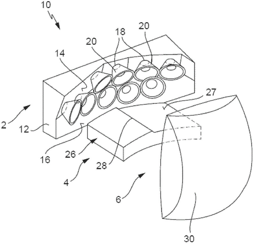
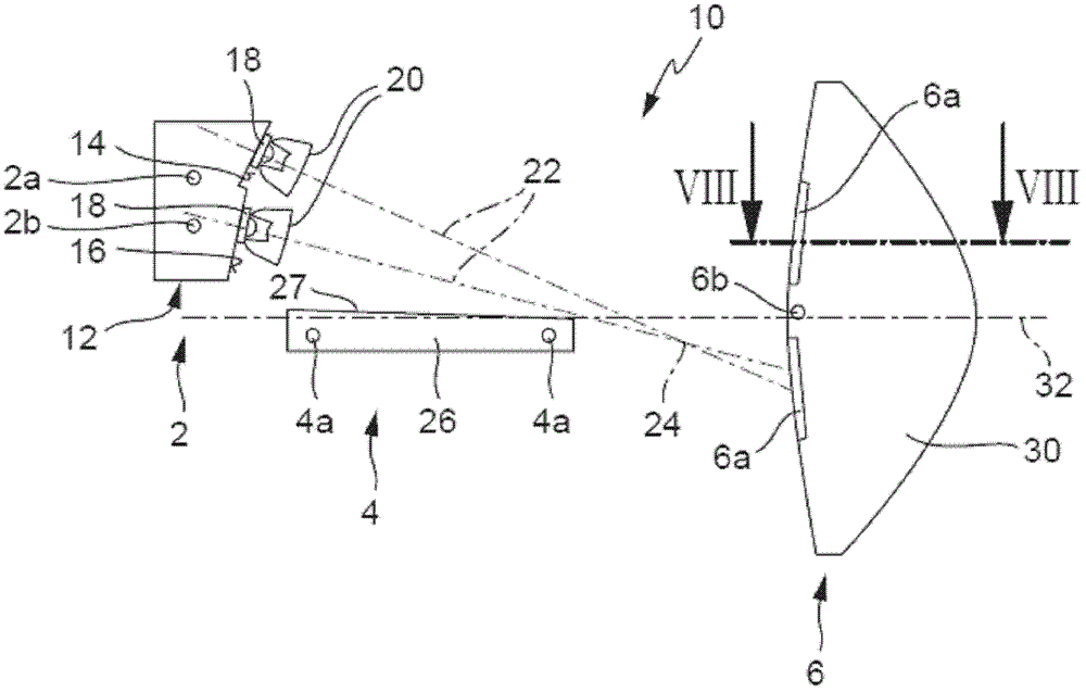
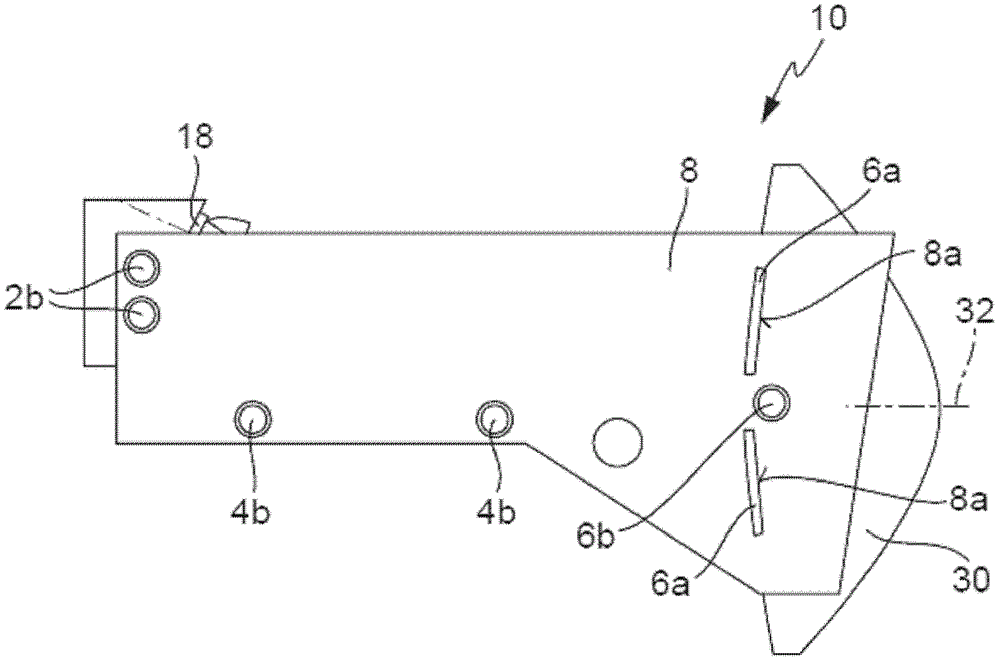
[0039] Generally, people divide the projection light module including semiconductor light sources into four functional groups from the perspective of manufacturing technology and design: these functional groups involve the light source unit, the visor unit, the lens holding unit and the lens unit. figure 1 and 2 The structures of the light source unit, the visor unit, and the lens unit are shown. image 3 These three functional groups are shown, in addition to the lens holding unit.

[0040] figure 1 The structures of the light source unit 2 , the visor unit 4 and the lens unit 6 of the light projection module 10 are shown in detail.

[0041] The light source unit 2 has a heat sink 12 made of a material having a high thermal conductivity, such as aluminum, magnesium, copper, or an alloy containing such metals. In one configuration, heat...


PUM


Abstract

The projection light module (10) comprises an assembly, which has a light source unit (2) with semiconductor light sources, and another assembly with a lens unit (6). The former assembly is configured to hold the latter assembly in the projection light module. The former assembly is configured to hold in the projection light module without changing an embodiment of the latter assembly or another embodiment of the latter assembly different from the former embodiment.

Description

technical field [0001] The invention relates to a projection light module, comprising at least one first assembly with a light source unit comprising a semiconductor light source and a second assembly with a lens unit, wherein the first assembly is arranged to incorporate the second Components remain in the projection light module. [0002] The second component is, for example, a lens unit, and the first component includes, for example, a light source unit, a visor unit, and a lens holding unit. Background technique [0003] Such projection light modules are known per se and are used to generate light distributions with light and dark boundaries for headlights. In this case, the light-dark boundary is produced as a projection of the shutter edge of the shutter unit which is illuminated by the light source of the light source unit. The appearance of the headlight represents an important identification mark of the motor vehicle. In order to differentiate its products from t...

Claims


Application Information

Patent Timeline
Patent Type & Authority Patents(China)
IPC IPC(8): F21S8/10F21V13/02F21W101/10F21Y115/10
CPCF21S41/147F21S41/153F21S41/19F21S41/285F21S41/295F21S41/47
Inventor 迈克尔·哈姆克里斯蒂安·巴克伯杰
Owner AUTOMOTIVE LIGHTING REUTLINGEN GMBH
Why Eureka
Try Eureka