Method and devices to minimize work-piece distortion due to adhering stresses and changes in internal stresses

a technology of which is applied in the field of methods and devices to minimize workpiece distortion due to adhesion stress and internal stress changes, can solve the problems of previously machined surfaces distorted, adhesion process exerting stress, and affecting the holding strength of adhesive fixtures, so as to reduce the effect of holding strength

Active Publication Date: 2019-07-02
BLUE PHOTON TECH & WORKHLDG SYST L L C
View PDF20 Cites 1 Cited by
  • Summary
  • Abstract
  • Description
  • Claims
  • Application Information

AI Technical Summary

Benefits of technology

[0040]An embodiment of the present invention discloses a method that may allow the work-piece to obtain its free state shape while bonded to the adhesive fixture. One embodiment requires the adhesive fixture to utilize a base and a plurality of fixing surfaces capable of changing shape and / or displacing relative to the base. The method comprises the steps of adjoining adhesive to a fixing surface; adhering the adhesive to a fixing surface and work-piece to create an adhesive bond between the two for the purpose of restraining the work-piece during a manufacturing process; and altering a fixing surface with a shape change and / or displacement to allow the work-piece to obtain an equilibrium shape closer to the free state, and not rupture the adhesive joint nor reduce its holding strength.
[0041]According to one embodiment, a method of holding a work-piece on an adhesive fixture includes providing a fixture having a fixture base and a plurality of fixing surfaces each capable of at least one of changing shape and displacing relative to the fixture base. Adhesive is adjoined to at least one of the plurality of fixing surfaces. The adhesive is adhered to the fixing surface and to a work-piece to create an adhesive joint between the fixing surface and work-piece to restrain the work-piece during a manufacturing process. The at least one fixing surface is altered with a shape change or displacement such that the work-piece is allowed to obtain an equilibrium shape closer to a free state without rupturing the adhesive joint or substantially reducing its holding strength.

Problems solved by technology

However in other applications they may not be.
Adhesive fixtures suffer two important limitations.
The first limitation is that the adhesion process can exert stresses that distort the work-piece 2 from its free state shape 8 as shown in FIG. 5.
This will cause the previously machined surfaces to distort, and possibly go out of tolerance.
In the case of a pressure sensitive adhesive, work-piece shape distortion is due to the flexure of the work-piece as it is being forced on to the adhesive.
When structural adhesives are used, work-piece distortion results from two phenomena occurring at the same time.
This is especially problematic for cases in which the three have significantly different coefficients of thermal expansion and when the adhesive must undergo a significant drop in temperature to solidify.
Work-piece distortion due to adhesive solidification increases with increased compliance of the relevant surface and an increase in residual stresses within the adhesive joint.
They also increase with decreased compliance of the fixing surface.
The second limitation of an adhesive fixture is the restraint that it provides to a work-piece distorted by an imbalance of internal residual stresses. FIG. 8 illustrates a work-piece 2 that was theoretically adhered to a fixture without the development of residual, adhesive stresses and consequently was in its free state shape.
Unfortunately the machining process removes a portion of these internal stresses, causing an imbalance, which also results in stresses arising in the adhesive joints.
However the restraint provided by the adhesive joints prevents this.
In this case, the machined surface is now distorted.
The big problem with this phenomena is that the geometry of a part must often be characterized while it is in the free state.
In many cases it is very difficult to eliminate work-piece shape distortion that results from the combination of adhesion stresses and imbalanced internal stresses.
All of this leads to increased manufacturing lead time and increased manufacturing cost.
In general, this problem is more significant if adhesive joints restrain surfaces that are highly compliant at any stage of the manufacturing process.
Unfortunately, compliant work-piece surfaces are the ones that are in the greatest need of support from an adhesive joint in order to counteract external stresses supplied by the manufacturing process.
Yet forming adhesive joints on these surfaces can cause significantly greater distortion than the manufacturing process.
While this process is suitable for welding, it is not particularly attractive for accurate work-holding.
Not only is it time consuming and cumbersome, but there is no guarantee it will lead to the desired result.
But none of these techniques address the second problem.
This is an effective technique, but it has a number of limitations.
It cannot be universally applied to all work-piece materials.
It is an added step that costs time and money.
Furthermore it cannot typically be applied while the part is held adhesively.
Most value added materials have stress relief temperatures which will destroy many practical work-holding adhesives.
They can also damage the adhesive fixture.

Method used


Image

  • Method and devices to minimize work-piece distortion due to adhering stresses and changes in internal stresses
  • Method and devices to minimize work-piece distortion due to adhering stresses and changes in internal stresses
  • Method and devices to minimize work-piece distortion due to adhering stresses and changes in internal stresses

Examples


Embodiment Construction

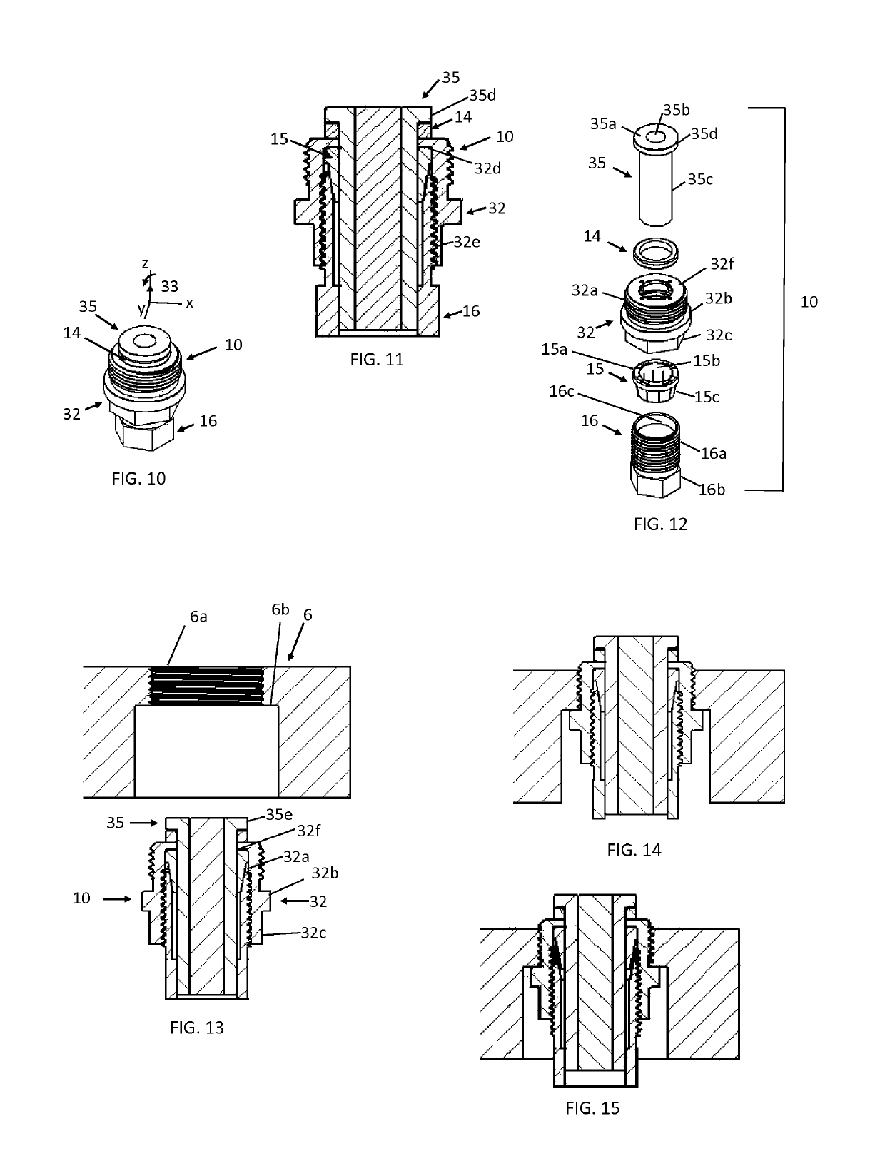
[0116]One component of this invention is the concept of a floating adhesive fixture device. Most embodiments of a floating adhesive fixture device include the following components:

[0117]1. An outer body that is affixed to a fixture base;

[0118]2. A solid, distinct fixture element with a fixing surface to adhere the work-piece and that can be displace relative to the outer body within a continuous, finite range and at any position within this range can have its displacement freedom stopped;

[0119]3. A clamping mechanism that can make contact with the fixture element while it is at any position within its prescribed range and in repeated fashion:

[0120]a) engage to prevent displacement of the fixing surface without significantly changing the fixing surface's position; and

[0121]b) disengage to allow the displacement freedom of the fixing surface;

[0122]4. A system of guides that allow the displacement of the fixture element to occur with selected d.d.o.f. along an extended range; and

[0123]...


PUM

PropertyMeasurementUnit
diameteraaaaaaaaaa
diameteraaaaaaaaaa
diameteraaaaaaaaaa

Abstract

A method of allowing a work-piece to obtain its free state shape while bonded to an adhesive fixture includes allowing the fixing surfaces to change shape or position relative to a fixture base without degrading the holding strength of the adhesive joints. A floating adhesive fixture may use one or more floating adhesive fixture devices. Each device includes a fixture element with an integral fixing surface that can displace relative to the fixture, a clamping system that can release or prevent this motion, and a suspension that keeps the fixture element in a nominal position when the clamping system is disengaged. A method includes unclamping the fixture elements and allowing them to displace as the adhesive joints and work-piece reduce strain energy. The clamping of the fixture elements prepares the fixture for the ensuing manufacturing process.

Description

CROSS-REFERENCE TO RELATED APPLICATIONS[0001]This application is a 371 national stage application claiming priority to international application No. PCT / US2015 / 041270, filed Jul. 21, 2015, which claims priority to U.S. patent application No. 62 / 027,293, filed Jul. 22, 2014, the contents of both of which are incorporated herein in their entirety.BACKGROUND OF THE INVENTION[0002]Adhesive fixtures are used extensively in manufacturing industries to hold work-pieces relative to fabrication processes, assembly processes, and inspection processes. The types of work-pieces held include solid work-pieces, locked-out assembled work-pieces, and semi-locked out assembled work-pieces. The principle advantages to using this type of fixture in comparison to mechanical clamping fixtures, magnetic chucks, vacuum chucks, and electric-static chucks are: 1) enhanced access to the work-piece, 2) selectable holding strength and stiffness via choice of the adhesive, 3) diversity in the work-piece shapes,...

Claims


Application Information

Patent Timeline
Patent Type & Authority Patents(United States)
IPC IPC(8): B29C65/48B23Q3/08B23Q1/03B29L31/00
CPCB29C65/48B23Q3/084B23Q1/035B29L2031/727
Inventor DE METER, EDWARD C.BILLINGS, DANIAL
Owner BLUE PHOTON TECH & WORKHLDG SYST L L C
Why Eureka
Try Eureka