Optical mapping apparatus

a technology of optical mapping and optical tracing, which is applied in the field of optical tracing apparatus, can solve the problems of reducing the efficiency of correctors, reducing system complexity, and affecting the use of patients, and achieves the effect of efficient us

Inactive Publication Date: 2007-03-01
KENT UNIVERITY OF +1
View PDF14 Cites 110 Cited by
  • Summary
  • Abstract
  • Description
  • Claims
  • Application Information

AI Technical Summary

Benefits of technology

[0088] Confocal C-scan images was used to guide OCT image acquisition along the transverse coordinate only. By being able to resolve structure in depth, the confocal image in such conventional arrangements looked like a superposition of all C-scans collected in the OCT channel. By applying AO, the C-scan of the retina could be “thinned” to 50 μm. Therefore, embodiments of the invention enable a confocal image to be efficiently used to guide the acquisition of a OCT image not only transversally but axially too.
[0089] Confocal microscopy can take advantage of the depth resolution improveme...

Problems solved by technology

However, important limitations still exist in imaging with high resolution the retina and tissue in histology.
As a disadvantage of the system disclosed, both reference beam and object beam from the interferometer traverse the wavefront corrector.
Both object and reference beams are routed via the wavefront corrector with disadvantages in terms of system complexity, and reduction in the corrector efficiency, as central actuators in the correctors are sacrificed to reflect the reference beam.
As another disadvantage, the OCT system in WO 2003/105678 operates as a full field time domain OCT, or coherence radar, where the 2D interference map of a reference local beam and an object beam returned from the object is displayed by a 2D CCD camera, which produces C-scan OCT images.
It is known that flood illumination imaging of the fundus is inferior to flying spot in terms of signal to noise ratio.
As another disadvantage, B-scan OCT images can only be produced after a stack of C-scan images have been collected from different depths, and by software means, a B-scan is inferred from the 3D volume of data, i.e. a B-scan cannot be produced in real time.
As another disadvantage of the Zhang system, the two images generated in sequential regime cannot be compared to each other.
As another disadvantage of the Zhang system, the fundus camera regime demonstrates improvement in the transverse resolution of C-scan images when AO is applied, but because no confocal aperture is used, the...

Method used


Image

  • Optical mapping apparatus
  • Optical mapping apparatus
  • Optical mapping apparatus

Examples


first embodiment

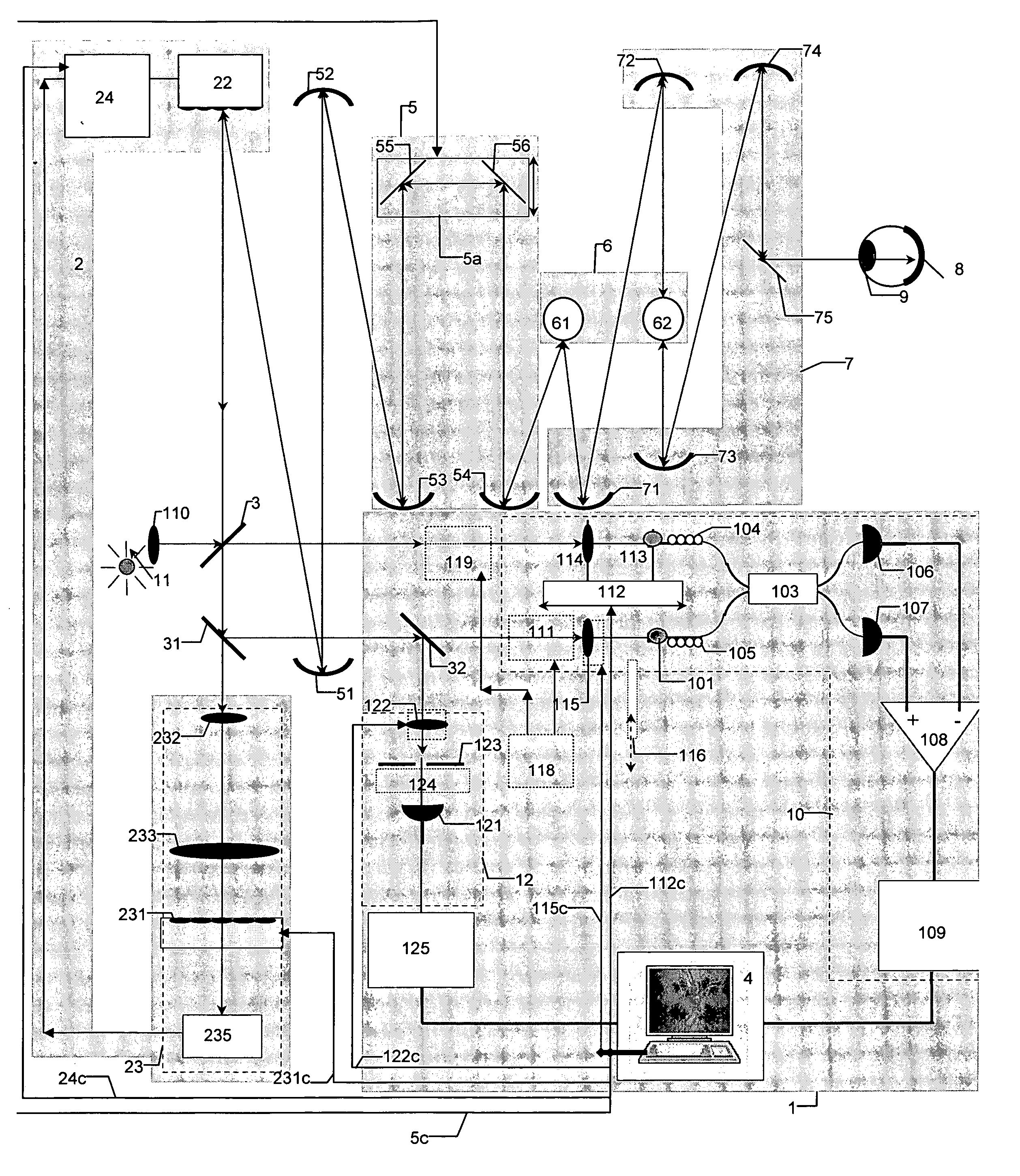
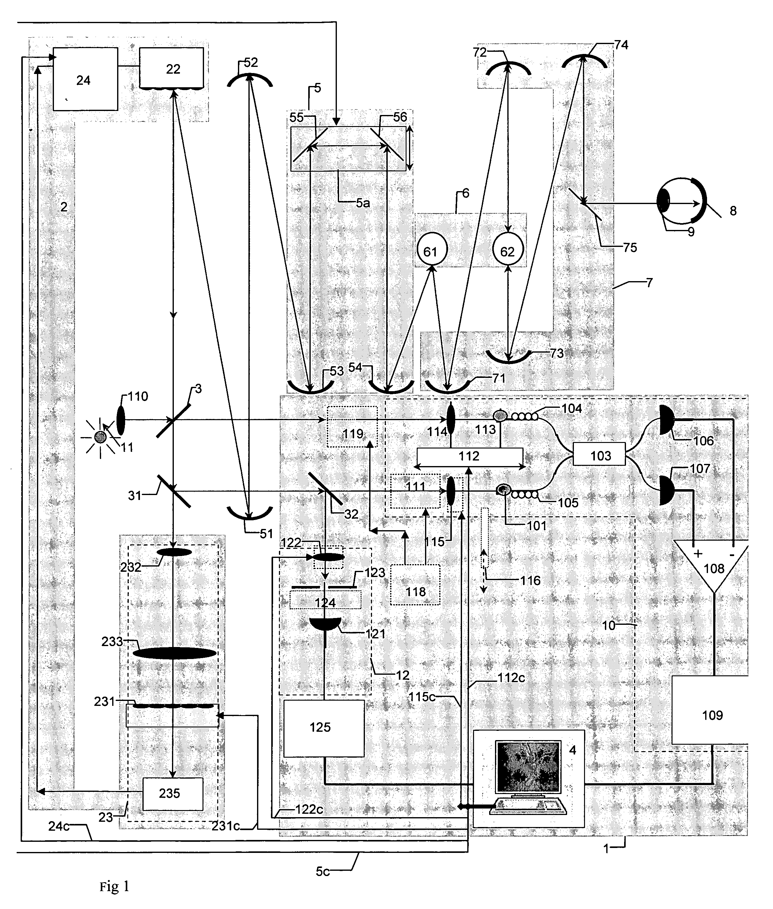
[0110]FIG. 1 shows the high resolution imaging system according to an embodiment of the invention. Light from a low coherence source 11 is collimated via focusing element 110 and divided by an OCT beamsplitter, 3 into two beams, a reference beam and an object beam. The object beam is sent towards a wavefront corrector 22, wherefrom the beam is transferred via the a telescope, equipped with curved mirrors 51, 52 towards focusing optics 5, constructed from curved mirrors 53, 54 and flat mirrors 55, 56 in a Badal configuration. The object beam is then sent to a transverse scanner 6, constructed from a line scanner 61 and a frame scanner 62. The scanner 6 is arranged to scan beams from the source 11 over a predetermined area. Interface optics 7, consisting of curved mirrors 71-74 and flat mirror 75 are provided to transfer a beam from the scanner 6 to the object to be imaged, 8. The curved mirrors 51-54 and 71-74 could be parabolic or spherical. In FIG. 1, the object 8 is the retina beh...

fifth embodiment

[0211]FIG. 6 shows the system for high resolution imaging, where a common focus element 110 is used for both OCT and confocal channels in the uncommon path. The OCT splitter 3 is in single mode fibre and tied by fibre to transfer light from the object 8 to the input 101 of the balanced splitter 103. The aperture of the confocal receiver at the core of the OCT is now at the fibre tip 106 of the fibre 126, behind the splitter 32. Light diverges out from the aperture fibre. 100. By axially moving the collimating element 110, the convergence of the beam sent to the interface optics 7 changes. The aperture of the OCT input, 100, is conjugate by virtue of beamsplitter 32 with the confocal aperture 106, here implemented in fibre 126, which could be single mode or multimode. Input 110 could be moved under computer, e,g, PC 4 control, showed by control line 110c. Irrespective of focus correction by elements 55 and 56, or the deformation of the corrector 22, the two fibre apertures 100 and 10...


PUM


Abstract

Optical mapping apparatus for imaging an object, comprising an optical coherence tomography (OCT) system including an OCT source, an OCT reference path leading from the OCT source to an OCT receiver, an OCT object path leading from the object to the OCT coupler, an OCT depth scanner adapted to alter at least one of the OCT reference path and the OCT receiver path. A confocal system is provided including a confocal optical receiver a confocal path leading from the object to the confocal optical receiver via a confocal input aperture. An adaptive optics (AO) system is provided to correct optical aberrations in the OCT object path and the confocal path.

Description

TECHNICAL FIELD OF THE INVENTION [0001] The present invention relates to an optical mapping apparatus and to methods which can be used to supply high resolution images from essentially transparent objects or tissue simultaneously or, sequentially, via aberrated paths. Confocal, fluorescence and optical coherence tomography channels are provided. In particular, but not exclusively, the invention relates to the imaging of ocular tissue. BACKGROUND OF THE INVENTION [0002] In the description which follows, reference is made primarily to the eye as the object. This has to be understood as merely a way to help the description and not as a restriction of the application of the present invention. As such, where the term “eye” is used, a more general transparent and scattering object or organ may be sought instead. In the case of the eye, the object is the retina which is to be imaged via the anterior chamber which introduces aberrations. When a specimen in microscopy is the object, the aber...

Claims


Application Information

Patent Timeline
IPC IPC(8): G01B11/02A61B3/12
CPCA61B3/102A61B3/14A61B3/1025
Inventor PODOLEANU, ADRIANBRADU, ADRIANDAINTY, CHRISMERINO, DAVID
Owner KENT UNIVERITY OF
Why Eureka
Try Eureka