Single frequency duplex radio link

a radio link and single frequency technology, applied in the field of single frequency duplex radio links, can solve the problems of limiting the useful range of the receiver and the distance over which full duplex radio communication can be carried out, and affecting the service life of the receiver

Inactive Publication Date: 2007-09-06
TREX ENTERPRISES CORP
View PDF9 Cites 112 Cited by
  • Summary
  • Abstract
  • Description
  • Claims
  • Application Information

AI Technical Summary

Benefits of technology

[0010]The present invention provides a radio link with two communicating transceivers each having a system for isolating incoming and outgoing radio signals to permit simultaneous transmit and receive by each transceiver on the same frequency or in the same frequency range. This is done so that in-coming receive signals received by each of the transceivers from the other transceiver is much stronger than the portion of its own transmitted signal that is coupled back into its antenna. The invention uses a special electronic circuit, termed the iso-circulator, to couple the antenna to both the co-located receiver and the transmitter. The iso-circulator circuit includes a simulated antenna load with an impedance matched to the antenna impedance. The circuit also includes a transformer with its primary side fed asymmetrically by the antenna so that it can pass the desired receive signal with minimum attenuation. The transformer's primary is on the other hand fed symmetrically from both sides by equally small portions of the transmit power from the co-site transmitter, but these signals are 180 degrees out of phase and cancel almost completely in the transformer. The iso-circulator works in an unsymmetrical manner as far as the desired receive signal is concerned and in a symmetrical manner as far as the undesired co-site transmit signal is concerned, so that the receiver connected to the secondary side of the transformer receives the desired signal from the remote radio at a much higher sensitivity than it receives the leakage portion of the co-site transmit signal. Thus the invention provides a reduction in excess of 60 to 70 dB in the strength of the co-site transmitter signal at the receiver input, while leaving the signal captured by the antenna reduced by only 1 dB at the input to the receiver electronics.

Problems solved by technology

If the transmitter power is not suppressed sufficiently at the receiver input, then the sensitivity of the receiver is deteriorated, even though operation may still be possible at some impractically high receive signal levels.
Power levels at the receiver input from communication signals captured by the antenna are often in the range of −90 to −20 dBm, so insufficient suppression of the transmitter output will limit the useful range of the receiver and the distance over which full duplex radio communication may be established.
The issues of co-site interference here are prevalent and enormous.
However, magnetic circulators are not available at all frequency ranges, especially at VLF, LF, HF, VHF and UHF bands, and even if available they do not cover a wide bandwidth and can not handle high power.
No prior art has been shown to adequately address interference mitigation for a system in which a co-sited transmitter is operating at the same frequency as the receiver.

Method used


Image

  • Single frequency duplex radio link
  • Single frequency duplex radio link
  • Single frequency duplex radio link

Examples


Embodiment Construction

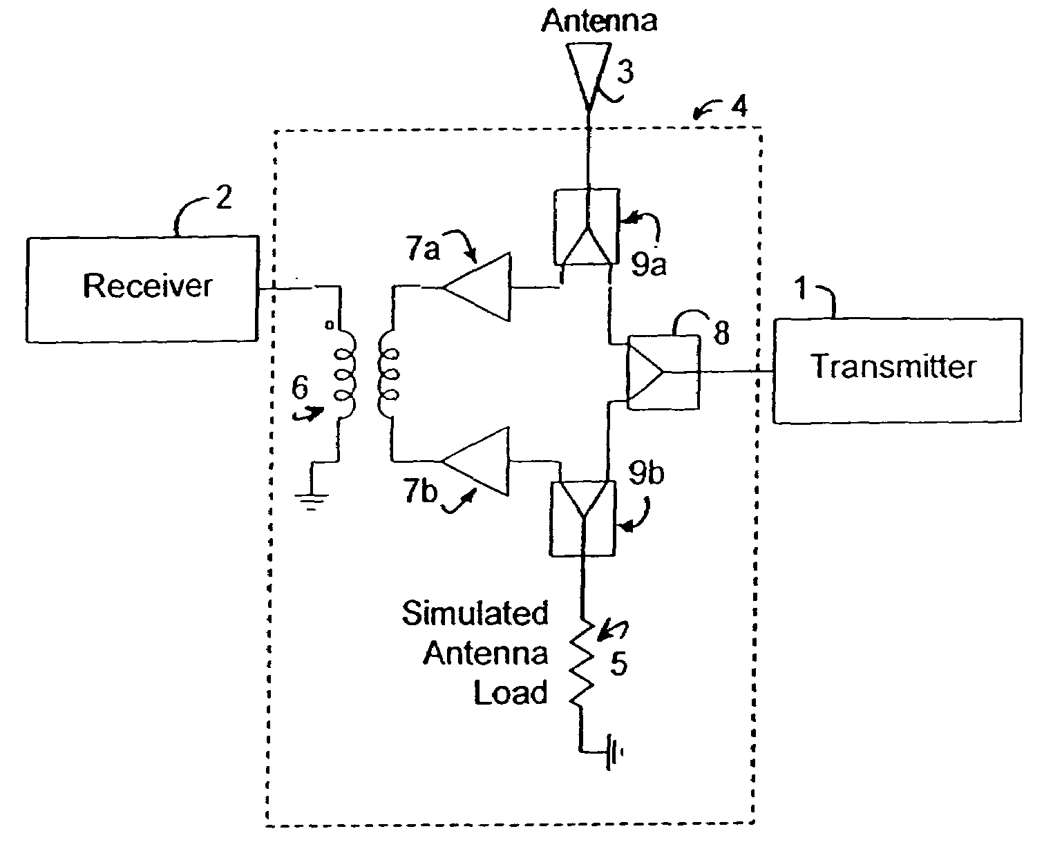
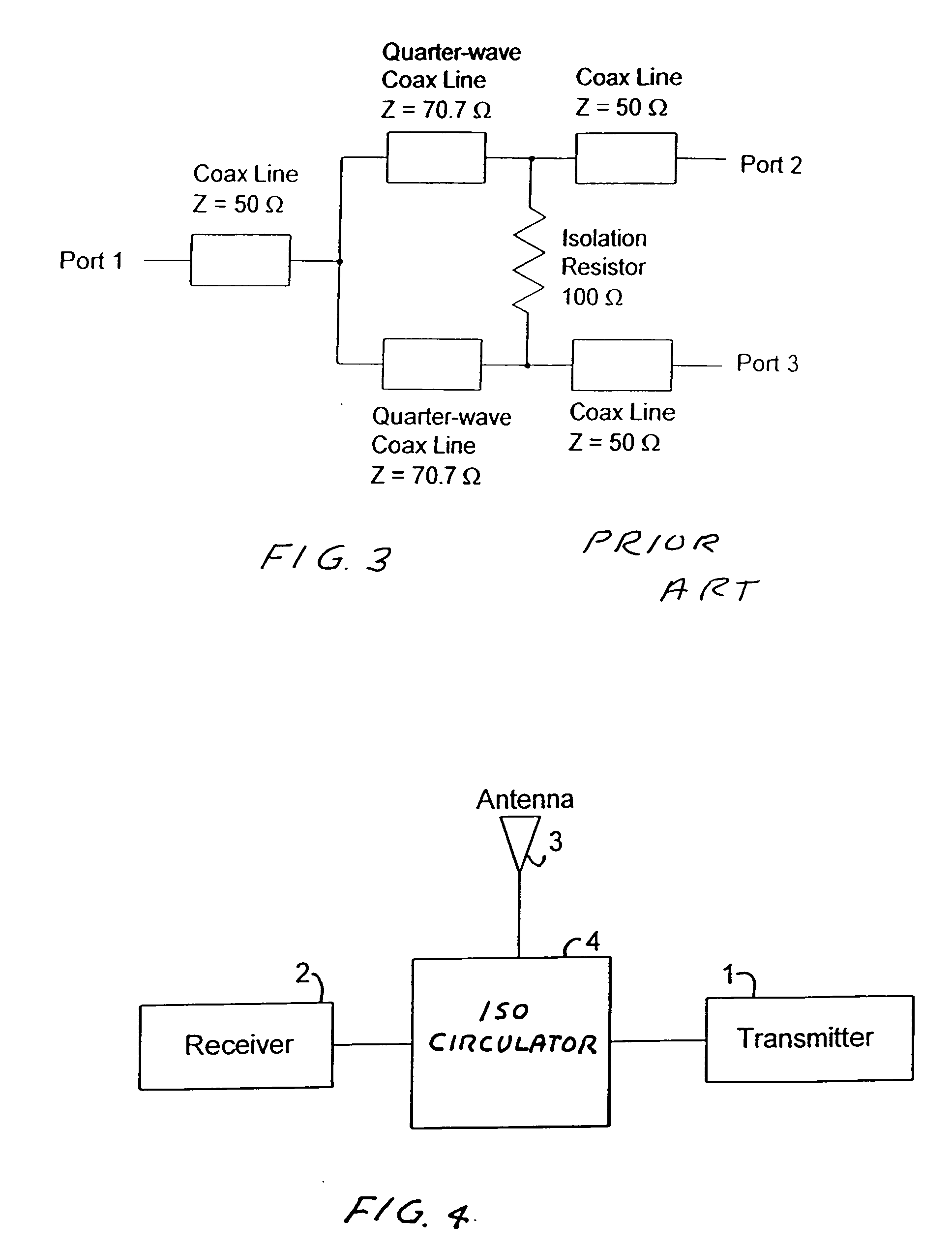
[0020]With reference to FIG. 4, the preferred embodiment of the present invention is comprised of radio transmitter 1, radio receiver 2, antenna 3, and ‘iso-circulator’4. In a preferred embodiment the radio would be configured to simultaneously transmit and receiver computer network data at 100 Mbps (each direction) in the license-free 2.4 GHz ISM (Industrial / Scentific / Medical) band. Transmitter 1 and Receiver 2 are in simultaneous operation, with transmitter 1 having a center frequency of 2435 MHz and receiver 2 having a center frequency of 2435 MHz. Different spread spectrum codes and modulation techniques for the transmitted and the received signals may be employed to further enhance the separation of the transmit and receive signals beyond the 70 dB that is achieved by iso-circulator 4.

[0021]Transmitter 1, receiver 2, and antenna 3 are available from a variety of vendors and are well know to those familiar with the industry. Iso-circulator 4 is a custom-developed design based on...


PUM


Abstract

A radio link with two communicating transceivers each having a system for isolating incoming and outgoing radio signals to permit simultaneous transmit and receive by each transceiver on the same frequency or in the same frequency range. This is done so that in-coming receive signals received by each of the transceivers from the other transceiver is much stronger than the portion of its own transmitted signal that is coupled back into its antenna. The invention uses a special electronic circuit, termed the iso-circulator, to couple the antenna to both the co-located receiver and the transmitter. The iso-circulator circuit includes a simulated antenna load with an impedance matched to the antenna impedance. The circuit also includes a transformer with its primary side fed asymmetrically by the antenna so that it can pass the desired receive signal with minimum attenuation. The transformer's primary is on the other hand fed symmetrically from both sides by equally small portions of the transmit power from the co-site transmitter, but these signals are 180 degrees out of phase and cancel almost completely in the transformer.

Description

[0001]This application claims the benefit of U.S. Provisional Applications No. 60 / 779,791 filed on Mar. 6, 2006, and is a continuation in part of U.S. patent application Ser. No. 11 / 603,582, filed Nov. 22, 2006. This invention relates to radio systems and in particular radio systems having features to minimize radio interference.BACKGROUND OF THE INVENTION[0002]In many radio communications systems it is desirable to maintain continuous bi-directional data transfer (full duplex operation) between two stations. Cellular telephone systems and wireless computer networking systems are examples of two such systems. Currently, in these applications, maintaining the full duplex mode of operation requires that the telephone or radio modem transmit on one frequency range (or band) and receive on another frequency range. This technique is termed frequency diversity. For instance, a cellular telephone may operate in a frequency range around a nominal 800 MHz. That range may extend from about 79...

Claims


Application Information

Patent Timeline
Patent Type & Authority Applications(United States)
IPC IPC(8): H04B1/44
CPCH04B1/52
Inventor JOHNSON, PAULDO, KY-HIEN
Owner TREX ENTERPRISES CORP
Why Eureka
Try Eureka