Two-dimensional scanning and reflecting device

A reflective device and two-dimensional scanning technology, which is applied in the direction of optics, instruments, electrical components, etc., can solve the problems of small output, small scanning angle, etc., and achieve the effect of simple structure

Inactive Publication Date: 2012-08-29
IND TECH RES INST
View PDF7 Cites 13 Cited by
  • Summary
  • Abstract
  • Description
  • Claims
  • Application Information

AI Technical Summary

Problems solved by technology

But also because of its small output, the scanning angle is small

Method used


Image

  • Two-dimensional scanning and reflecting device
  • Two-dimensional scanning and reflecting device
  • Two-dimensional scanning and reflecting device

Examples


Embodiment Construction

[0062] The detailed features and advantages of the present invention will be described in detail below in the embodiments, the content of which is sufficient for any person skilled in the art to understand the technical content of the present invention and implement it accordingly, and according to the content disclosed in this specification, the scope of claims and the appended FIG. 1 , any person skilled in the art can easily understand the related objects and advantages of the present invention.

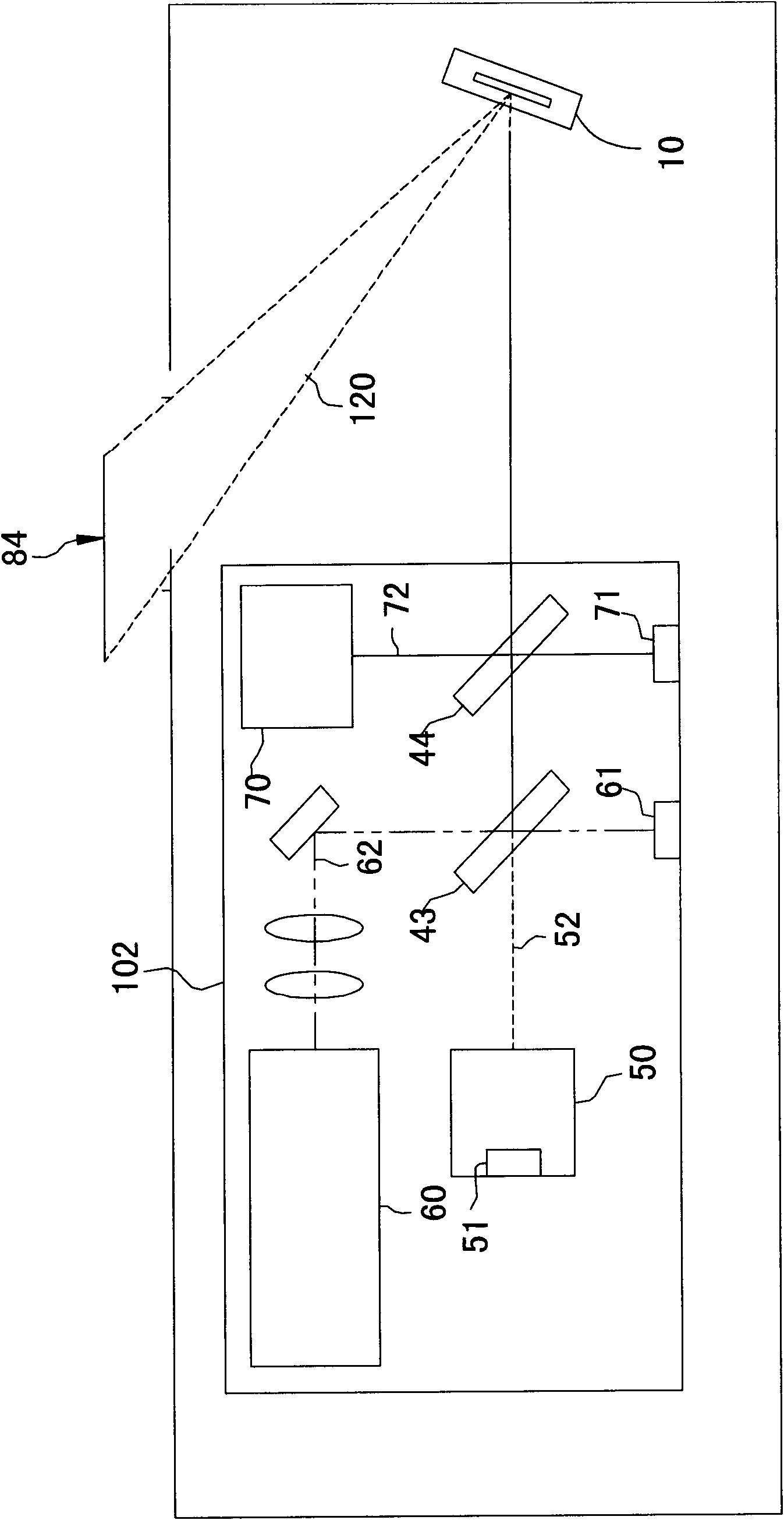
[0063] Please refer to figure 1 , is a schematic diagram of the structure of the optical scanning projection system of the present invention. The two-dimensional scanning reflective device 10 can be applied to mobile projection devices, such as but not limited to mobile phones or personal digital assistants. The mobile projection device may include but not limited to the scanning light source element 102 and the two-dimensional scanning reflection device 10 .

[0064] The reflec...


PUM


Abstract

A two-dimensional scanning and reflecting device includes a vibration component and a scanning component. The vibration component has a free end. The scanning component includes a frame body, a mass block, and a mirror. The frame body is connected to the free end of the vibration component. A natural frequency of the mirror corresponds to a second frequency. The mass block is disposed on the frame body in an eccentric manner, and the mass block and the natural frequency of the mirror correspond to a first frequency. When the vibration component receives a multi-frequency signal having the first frequency and the second frequency, the mirror vibrates in an axial direction with the first frequency, and vibrates in another axial direction with the second frequency.

Description

technical field [0001] The invention relates to a scanning reflection device, in particular to a two-dimensional scanning reflection device. Background technique [0002] At present, the mainstream of electronic products is light, thin, small and portable, and almost all components are going to be miniaturized, so the micro projector was born. At present, micro-projectors can be divided into three different technologies. One is laser micro-projection technology, which uses laser as a light source and uses MEMS technology to manufacture extremely small micro-scanning mirrors. Micro-scanning mirrors It can scan horizontally and vertically, and reflect laser light in a high-speed and precise manner to form projection imaging. The second is digital light source processing (DLP) technology. The image is generated by a digital micromirror device (Digital Micromirror Device, DMD). DMD is a matrix composed of microlenses (precise, miniature mirrors) arranged on a semiconductor chip...

Claims


Application Information

Patent Timeline
Patent Type & Authority Applications(China)
IPC IPC(8): G02B26/10H02N2/00
CPCH02N2/0015H02N2/108G02B26/0858G02B26/101H10N30/2041
Inventor 张平陈重德叶建贤李鸿忠
Owner IND TECH RES INST
Why Eureka
Try Eureka