

Operation assembly
A component and operation panel technology, which is applied in the direction of contact operation parts, etc., can solve the problems of uneven operation feeling of operation keys and weak reaction force of twisting parts, etc.
- Summary
- Abstract
- Description
- Claims
- Application Information
AI Technical Summary
Problems solved by technology
Method used
Image

Examples
Embodiment Construction
[0017] A fuller appreciation of the invention and its advantages will be more readily understood from the following detailed description of the invention, taken with reference to the accompanying drawings.
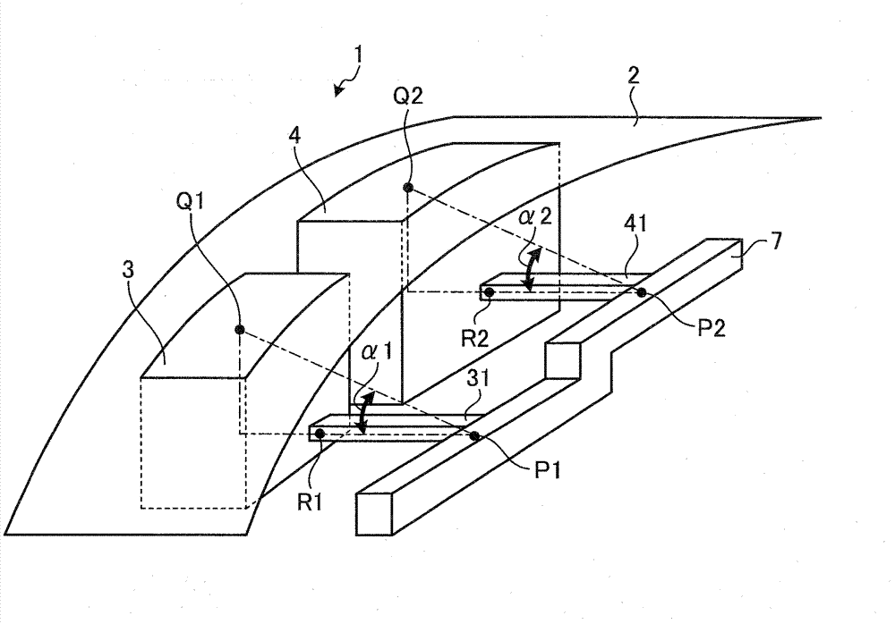
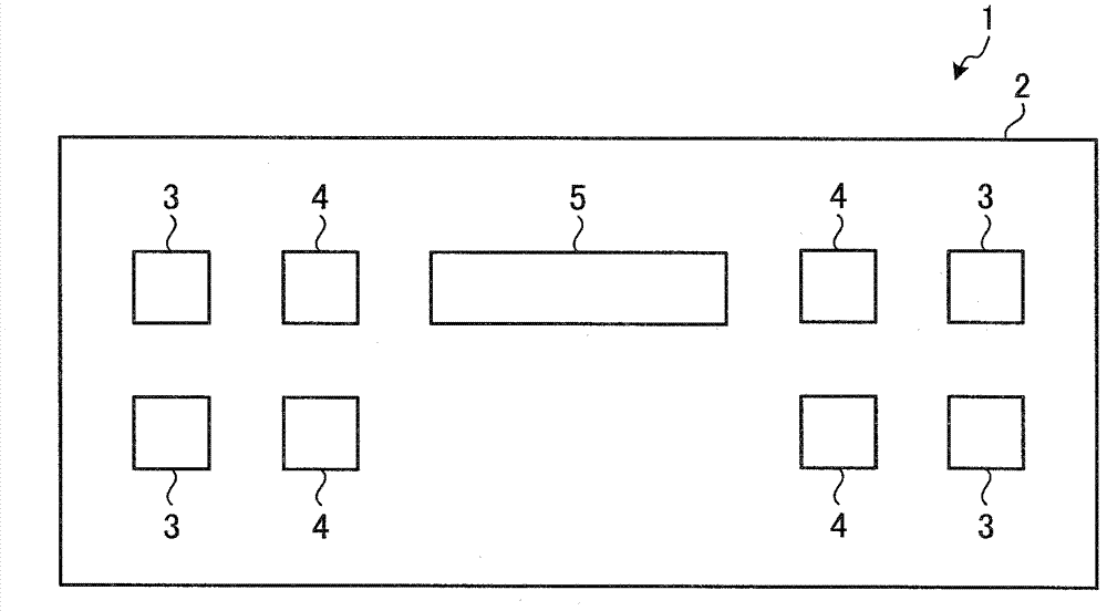
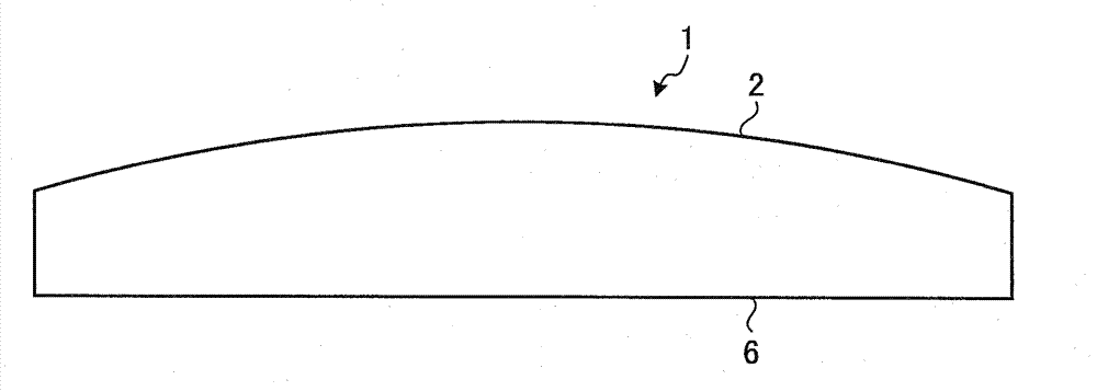
[0018] An operation unit according to an embodiment includes a plurality of operation keys, a fixing portion, and a connecting portion. A plurality of operation buttons are arranged along the curved operation panel. The fixing part is provided in a step shape along the back surface of the operation panel. The elastic connection part connects the operation button and the fixing part.
[0019] Hereinafter, embodiments of the operating unit according to the present invention will be described in detail with reference to the drawings. Also, the following, in use figure 1 After explaining the outline of the operation unit related to the embodiment, use Figure 2A ~ Figure 6 The operating components involved in the embodiment will be described in detail. Hereinafter, the op...
PUM
 Abstract
Description
Claims
Application Information