

Three-dimensional flow field image measurement device and method adopting single lens
A three-dimensional flow field and image measurement technology, which is used in measurement devices, testing of machine/structural components, fluid dynamics tests, etc. The effect of simplifying the measurement system and data processing process and reducing the cost of the system
- Summary
- Abstract
- Description
- Claims
- Application Information
AI Technical Summary
Problems solved by technology
Method used
Image

Examples
specific Embodiment approach
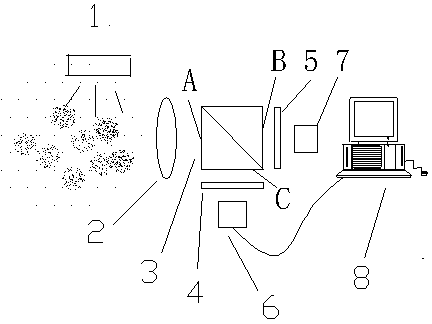
[0030] Embodiment 1 of a three-dimensional flow field image measurement device using a single lens, such as figure 1 As shown, it is characterized in that the device is composed of a polarized light source 1, a lens 2, a dichroic prism 3, a first polarizer 4, a second polarizer 5, a first image sensor 6, a second image sensor 7 and a computer 8, the described The polarized light source 1 is placed on the flow field to be measured to illuminate the flow field through the window, the beam splitting prism 3 is placed behind the lens 2, the incident surface A of the beam splitting prism 3 is opposite to the lens 2, and the first exit surface B of the beam splitting prism 3 The second image sensor 6 and the first image sensor 7 which are arranged at the same optical distance from one side of the second exit surface C respectively, and the first polarizer 4 and the second polarizer 5 are arranged on the second side of the dichroic prism 3 respectively. The middle between the exit s...
Embodiment 2
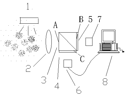
[0046] For example, the first polarizer 4 and the second polarizer 5 in embodiment 1 are coated on the two surfaces of the second exit surface C and the first exit surface B of the dichroic prism by coating, as figure 2 As shown, the dichroic prism 3 , the first polarizer 4 and the second polarizer 5 in the first embodiment are integrated, and the measurement steps are the same as those in the first embodiment.
Embodiment 3
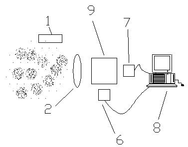
[0048] Such as image 3 As shown, the dichroic prism 3, the first polarizer 4 and the second polarizer 5 in the embodiment 1 can also be replaced by the polarization beam splitter prism 9, and the first image sensor 6 and the second image sensor 7 are then at an equal optical path distance They are respectively placed on the sides of the two outgoing surfaces of the polarizing beam splitter prism 9, and the measurement steps are the same as those in Embodiment 1.
PUM
 Abstract
Description
Claims
Application Information