Tamper circuit based on STM32 chip

A chip and anti-dismantlement technology, applied in the field of electronic information, can solve the problems of inability to accurately control the discharge time of the power supply, prone to mis-locked machines, power mis-locked machines, etc., so that the anti-dismantlement time can be easily adjusted and controlled, and the anti-dismantlement sensitivity can be guaranteed , the effect of prolonging the service life

Active Publication Date: 2013-01-02
FUJIAN CENTM INFORMATION
View PDF6 Cites 9 Cited by
  • Summary
  • Abstract
  • Description
  • Claims
  • Application Information

AI Technical Summary

Problems solved by technology

[0002] At present, some terminal devices related to security requirements have anti-dismantle function. In order to ensure that the anti-dismantle function of the terminal device is still effective when the power is off, it is generally realized by button batteries and RTC chips. The RTC chip is a high-precision Real-time clock IC (English full name of RTC: Real Time Clock, Chinese name: real-time clock; IC Chinese name: chip), which will increase the cost of terminal equipment, and because the button battery is directly connected to the power pin of the RTC chip, only by connecting the RTC power supply The decoupling capacitor of the foot cannot accurately control the discharge time of the power supply. If the discharge time is too short, the vibration and drop will cause the power supply to be disconnected instantaneously, and the machine will easily be locked by mistake. If the discharge time is too long, the machine will not be locked. It is not easy to control, and it is easy to accidentally lock or not lock the machine

Method used


Image

  • Tamper circuit based on STM32 chip

Examples


Embodiment Construction

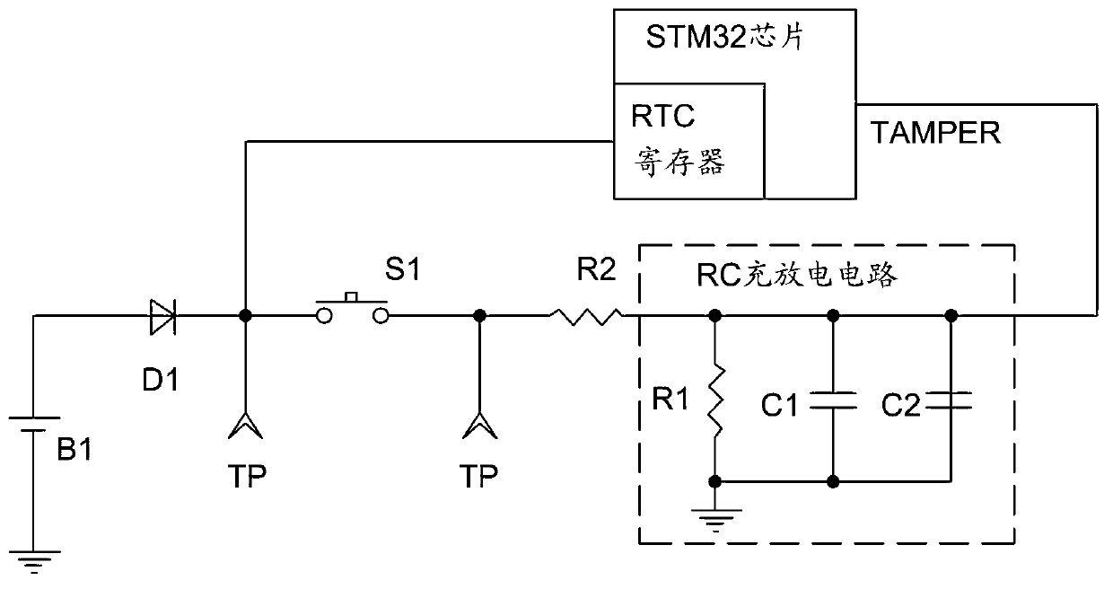
[0013] see figure 1 As shown, a tamper-resistant circuit based on the STM32 chip includes a battery B1, a switch S1, and an RC charging and discharging circuit. The battery B1 is respectively connected to one end of the switch S1 and the RTC register inside the STM32 chip. The battery B1 supplies power to the RTC register, the other end of the switch S1 is connected to one end of the RC charging and discharging circuit, and the other end of the RC charging and discharging circuit is connected to the TAMPER pin of the STM32 chip. Install the switch S1 in a certain place of the terminal equipment that is closed under normal conditions and disconnected in case of dismantling, for example, the anti-dismantle switch is on the motherboard, and the switch contacts are on the shell. When the terminal equipment is installed normally, the contacts Push against the anti-tamper switch, the switch is closed, after the terminal is disassembled, the contacts leave the anti-tamper switch, and...


PUM


Abstract

The invention provides a tamper circuit based on an STM32 chip. The tamper circuit comprises a battery, a switch and a resistor-capacitor (RC) charge-discharge circuit, wherein the battery is respectively connected with one end of the switch and a real time clock (RTC) register in the STM32 chip and supplies power for the RTC register, the other end of the switch is connected with one end of the RC charge-discharge circuit, and the other end of the RC charge-discharge circuit is connected with a TAMPER pin of the STM32 chip. According to the tamper circuit, additional chips (ICs) are not required to be added to achieve tamper functions, the tamper time is easy to control, and the tamper circuit is high in tamper sensitivity, low in cost, good in performance and interference resistance characteristics and long in service life of the battery.

Description

【Technical field】 [0001] The invention relates to the field of electronic information, in particular to a tamper-resistant circuit based on an STM32 chip. 【Background technique】 [0002] At present, some terminal devices related to security requirements have anti-dismantle function. In order to ensure that the anti-dismantle function of the terminal device is still effective when the power is off, it is generally realized by button batteries and RTC chips. The RTC chip is a high-precision Real-time clock IC (English full name of RTC: Real Time Clock, Chinese name: real-time clock; IC Chinese name: chip), which will increase the cost of terminal equipment, and because the button battery is directly connected to the power pin of the RTC chip, only by connecting the RTC power supply The decoupling capacitor of the foot cannot accurately control the discharge time of the power supply. If the discharge time is too short, the vibration and drop will cause the power supply to be di...

Claims


Application Information

Patent Timeline
Patent Type & Authority Applications(China)
IPC IPC(8): G05F1/46
Inventor 胡亚方张登峰余杭军
Owner FUJIAN CENTM INFORMATION
Why Eureka
Try Eureka