Axial-mode cylindrical helical antenna

A technology of helical antenna and axial mode, which is applied in the direction of antenna, resonant antenna, and mid-position feeding between antenna terminals, which can solve the problems of large size, complex feeding structure, and increase in the overall height of the helical antenna, and achieve the performance of the antenna. Excellent, simple physical structure, wide application effect

Inactive Publication Date: 2014-11-05
DALIAN MARITIME UNIVERSITY
View PDF6 Cites 0 Cited by
  • Summary
  • Abstract
  • Description
  • Claims
  • Application Information

AI Technical Summary

Problems solved by technology

As we all know, the size of the antenna basically determines the size of the wireless communication device. While continuously pursuing the miniaturization of the wireless communication device, it is of practical significance to improve the performance of the antenna and further reduce the size of the antenna; The design of the cylindrical helical antenna first selects the appropriate circumference and pitch according to the center frequency, and increases the gain by increasing the number of helical turns, which will increase the total height of the helical antenna; use the current truncation effect of the helical antenna to geometrically truncate the The helical part of the antenna reduces the height of the antenna, but a small number of helical turns deteriorates the circular polarization performance of the antenna; although the antenna structure with exponentially variable pitch improves the circular polarization radiation characteristics of the antenna, it is large in size and feeds The electrical structure is complex, and the limitation on the height of the antenna in practical applications is not considered

Method used


Image

  • Axial-mode cylindrical helical antenna
  • Axial-mode cylindrical helical antenna
  • Axial-mode cylindrical helical antenna

Examples


Embodiment Construction

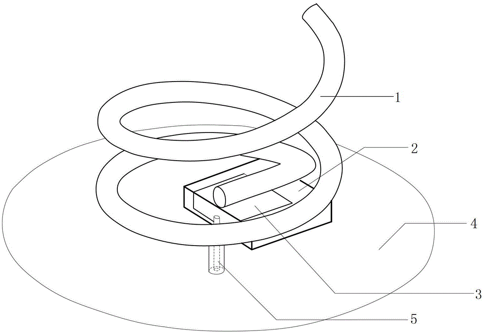
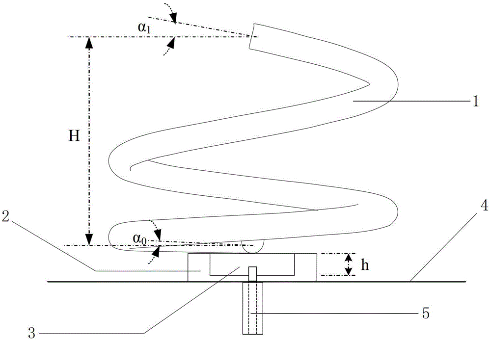
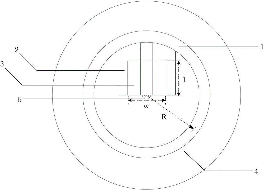
[0017] Such as figure 1 , figure 2 with image 3 An axial-mode cylindrical helical antenna shown includes a helical radiator 1, a dielectric support 2, a feeding matching body 3, a ground plate 4, and a radio frequency coaxial connector 5; The helical radiator 1 starts from the center of the bottom surface of the cylinder and extends radially to the circumference of the bottom surface, and then rises and extends in the axial direction to form a helical structure with a variable lift angle; the medium support body 2 is fixed on the above the ground plate 4; the feeding matching body 3 is an inverted L-shaped microstrip structure, which is divided into a horizontal part and a vertical part; the vertical part is adhered to the side of the dielectric support body 2; the spiral radiator 1 The starting end is arranged on the horizontal part adhered to the upper surface of the dielectric support body 2, and is held up by the dielectric support body 2; the radio frequency coaxial j...


PUM


Abstract

The invention discloses an axial-mode cylindrical helical antenna. The axial-mode cylindrical helical antenna comprises a helical radiator, a medium supporter, a feed matcher, a grounding board and a radio-frequency (RF) coaxial connector, wherein the helical radiator is of a cylindrical shape which is formed in a manner that a copper pipe is sequentially and helically encircled rightwards, and a variable-lift-angle helical structure is formed in a manner that the helical radiator extends to the circumference of a cylindrical bottom face from the circle center of the bottom face along the radial direction and then extends along the axial direction in a rising manner; the medium supporter is fixedly arranged on the grounding board; the feed matcher is of an inverted-L-shaped microstrip structure and divided into a horizontal part and a vertical part; the starting end of the helical radiator is arranged on the horizontal part which is stuck to the upper surface of the medium supporter and supported by the medium supporter; the RF coaxial connector is vertically arranged on the grounding board, and the top end of an inner conductor of the RF coaxial connector is connected with the vertical part; and an outer conductor of the RF coaxial connector is connected with the grounding board. The axial-mode cylindrical helical antenna has the advantages of flexible design, simple physical structure, excellent antenna performance and wide application.

Description

technical field [0001] The invention relates to an axial mode cylindrical helical antenna. Background technique [0002] As the front-end component of radio frequency communication, the antenna occupies an important position in the communication system. Its reasonable physical structure and excellent antenna performance not only guarantee the improvement of system performance but also help to save costs. The helical antenna is a kind of Antennas with a helical shape made of metal, depending on the main radiation direction of the antenna, mainly have two radiation modes, the normal mode and the axial mode. The axial mode helical antenna has a wide frequency band, high gain and low axial ratio. Features, so that it has been widely used in satellite communications. As we all know, the size of the antenna basically determines the size of the wireless communication device. While continuously pursuing the miniaturization of the wireless communication device, it is of practical si...

Claims


Application Information

Patent Timeline
Patent Type & Authority Patents(China)
IPC IPC(8): H01Q9/27H01Q13/08
Inventor 傅世强房少军周月
Owner DALIAN MARITIME UNIVERSITY
Why Eureka
Try Eureka