LED (light-emitting diode) fluorescent lamp drive circuit and LED lamp tube

A technology of LED fluorescent lamps and driving circuits, which is applied in the field of LED lamp tubes, can solve problems such as poor compatibility, and achieve the effects of strong compatibility, strong adaptability, and convenient use

Inactive Publication Date: 2013-02-13
浙江恒曼光电科技有限公司
View PDF11 Cites 77 Cited by
  • Summary
  • Abstract
  • Description
  • Claims
  • Application Information

AI Technical Summary

Problems solved by technology

[0010] Aiming at the shortcomings of poor compatibility in the prior art, the present invention provides an electronic ballast with high compatibility, not only comp

Method used


Image

  • LED (light-emitting diode) fluorescent lamp drive circuit and LED lamp tube
  • LED (light-emitting diode) fluorescent lamp drive circuit and LED lamp tube
  • LED (light-emitting diode) fluorescent lamp drive circuit and LED lamp tube

Examples


Example Embodiment

[0037] Example 1

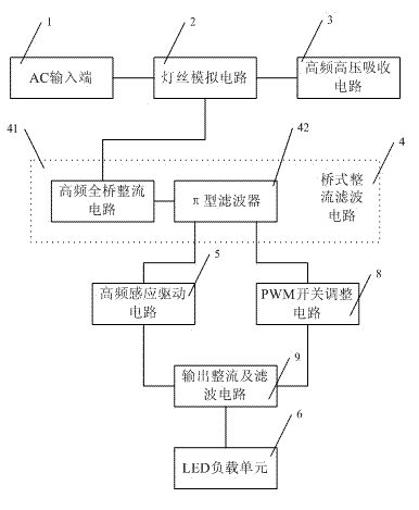
[0038] LED fluorescent lamp drive circuit, such as figure 1 As shown, it includes an AC input terminal 1, a bridge rectifier filter circuit 4, an LED load unit 6, a filament simulation circuit 2, a high-frequency and high-voltage absorption circuit 3, and a high-frequency induction driving circuit 5.

[0039] Among them, such as Figure 5 As shown, the AC input terminal 1 includes input terminals L1, L2, N1, N2; the filament simulation circuit 2 includes resistors RX1, RX2, RX3, and RX4; the high-frequency and high-voltage absorption circuit 3 includes an inductor L3A, high-frequency Capacitor C3; the bridge rectifier filter circuit 4 includes a high-frequency full-bridge rectifier circuit 41, a common mode inductor L1, a π-type filter 42, a varistor VR1; the high-frequency induction drive circuit 5 includes an inductor L3B, resistors R5, R6 , R7, R8, R9, R10', R26, R27, R28, R29, rectifier diodes D5, D6, D12, D13, D14, D16, filter capacitor C8, capacitor C11, C1...

Example Embodiment

[0047] Example 2


PUM


Abstract

The invention relates to an LED (light-emitting diode) fluorescent lamp drive circuit, and discloses the LED fluorescent lamp drive circuit. The LED fluorescent lamp drive circuit comprises an AC (alternating current) input end, a bridge rectifier-filter circuit and an LED load unit. The LED fluorescent lamp drive circuit is characterized by also comprising a filament analogue circuit, a high-frequency and high-voltage absorption circuit and a high-frequency induction drive circuit. The LED fluorescent lamp drive circuit has the advantages of concise structure and good compatibility, and can be compatible with an electronic ballast and an alternating current electric supply.

Description

technical field [0001] The invention relates to an LED fluorescent lamp drive circuit, in particular to an LED fluorescent lamp drive circuit compatible with various high-efficiency high-frequency electronic ballasts and an LED lamp tube thereof. Background technique [0002] With the popularization of energy saving and consumption reduction and green environmental protection concepts, LED lights are welcomed by consumers for their low energy consumption, soft light source, high luminous brightness and small size. Several designs of driving circuits for LED fluorescent lamps have been disclosed in the prior art. [0003] The invention patent application with the application number 200910238994.X discloses "an LED drive circuit for lighting", including a high-frequency full-bridge rectifier, which uses the original rectifier of the fluorescent tube to realize lossless constant current power supply to the LED light string. [0004] The utility model patent with the applicatio...

Claims


Application Information

Patent Timeline
IPC IPC(8): H05B37/02
Inventor 祝增喜郝庆国徐丽芳
Owner 浙江恒曼光电科技有限公司
Why Eureka
Try Eureka