Steel tube bending machine

A bending machine and steel pipe technology, applied in the field of steel pipe bending machines, can solve problems such as low efficiency and irregular bending of artificial steel pipes, and achieve the effect of speeding up the construction progress and consistent arc

Inactive Publication Date: 2013-03-06
CHINA COAL NO 68 ENG COMPANY
View PDF7 Cites 11 Cited by
  • Summary
  • Abstract
  • Description
  • Claims
  • Application Information

AI Technical Summary

Problems solved by technology

[0003] The purpose of the present invention is to provide a steel pipe bending machine to solve the technical problems of irregular bending and low efficiency of artificial steel pipes

Method used


Image

  • Steel tube bending machine

Examples


Embodiment Construction

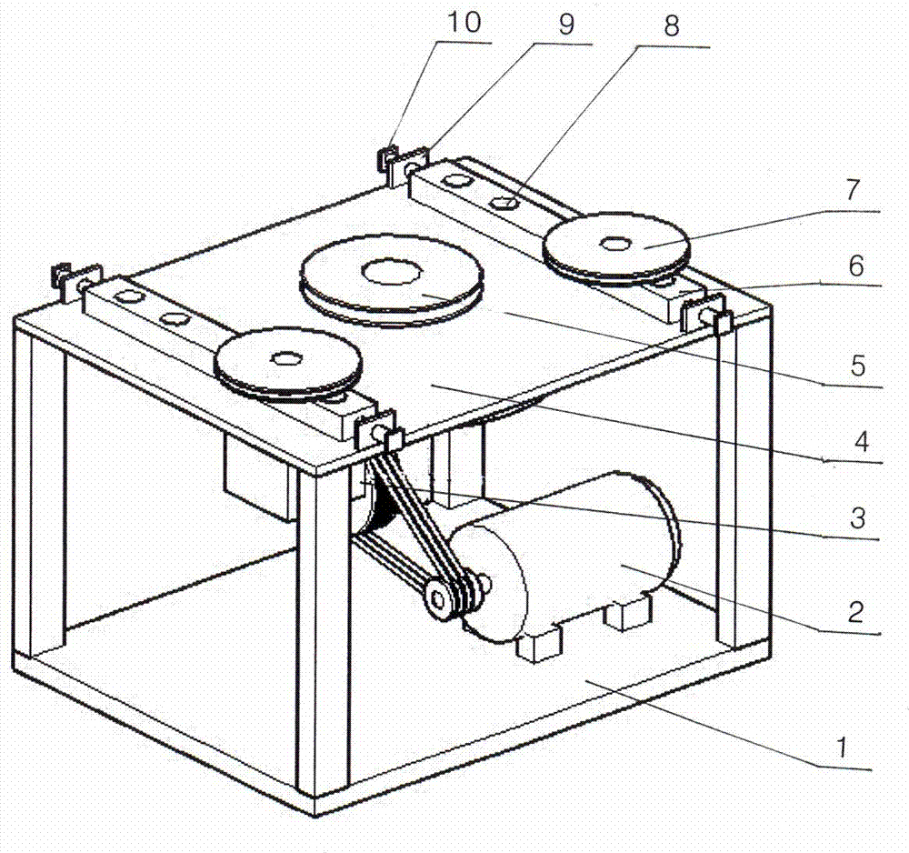
[0009] refer to figure 1 , there is a frame 1, a table 4 is arranged on the top of the frame 1, and a horizontal driving wheel 5 is set through the axle support in the middle of the table 4, and the reduction box 3 is fixed below the table 4, and the output shaft of the reduction box 3 and the driving wheel 5 The motor 2 is installed on the frame 1, the output shaft of the motor 2 is connected with the input shaft of the reduction box 3, and the sliding plate 6 is set on the slideway on both sides of the driving wheel 5 on the table 4, corresponding to the table 4. The top plate 9 is fixed at both ends of the sliding plate 6, and an adjusting bolt 10 is arranged on the top plate 9, and the front end of the adjusting bolt 10 is pushed against the end of the sliding plate 9; a number of supporting holes 8 are arranged on the sliding plate 9, and some supporting shafts are provided. The driven wheel 7, the supporting shaft of the driven wheel 7 is inserted in one of the supportin...


PUM


Abstract

The invention discloses a steel tube bending machine. A table top is arranged at the upper part of a rack; a horizontal driving wheel is arranged in the middle part of the table top through a wheel axle in a supporting manner; a speed reducing box is fixed at the lower side of the table top; an output shaft of the speed reducing box is connected with wheel and axle power of the driving wheel; the rack is provided with an electromotor; the output shaft of the electromotor is connected with power of an input shaft of the speed reducing box; the two sides of the driving wheel on the table top are respectively provided with a driven wheel; the outer peripheries of the driving wheel and the driven wheels are provided with semicircular grooves; slideways at the two sides of the driving wheel on the table top are respectively provided with a sliding plate; the two ends of the table top corresponding to the sliding plates are fixedly provided with a top plate; an adjustment bolt is arranged on the top plate; the front end of the adjustment bolt presses against the front parts of the sliding plates; a plurality of support holes are distributed on the sliding plates; and support shafts of the driven wheels are inserted into the support holes on the sliding plates. The steel tube bending machine is used for the working procedure of bending hollow steel tubes; the working procedure can be independently finished only by one person; the radian of the bent steel tubes is consistent, and the time and labor are saved, so that the construction progress is accelerated.

Description

technical field [0001] The invention relates to a steel pipe bending machine, which is used for the bending process of hollow steel pipes. Background technique [0002] When bending hollow steel pipes, the general construction work is to use steel pipes to build a steel pipe frame for bending, and then manually bend the straight steel pipes on the built frame. And steel pipe trimming time, when bending steel pipes in large quantities, manual bending is far behind the progress of the project. Contents of the invention [0003] The object of the present invention is to provide a steel pipe bending machine to solve the technical problems of irregular bending and low efficiency of artificial steel pipes. [0004] The purpose of the present invention is achieved in the following way: there is a frame, the top of the frame has a table top, the horizontal drive wheel is set through the axle support in the middle of the table top, the reduction box is fixed below the table top, a...

Claims


Application Information

Patent Timeline
Patent Type & Authority Applications(China)
IPC IPC(8): B21D7/08
Inventor 井立祥牟守臣毕军思聂思章
Owner CHINA COAL NO 68 ENG COMPANY
Why Eureka
Try Eureka