Method for cutting groove by utilizing laser and laser cutting machine

A technology of laser cutting machine and bevel cutting, which is applied to laser welding equipment, welding equipment, metal processing equipment, etc., and can solve problems such as inability to complete bevel cutting

Active Publication Date: 2013-04-03
SHENZHEN HANS MP LASER TECH CO LTD
View PDF10 Cites 7 Cited by
  • Summary
  • Abstract
  • Description
  • Claims
  • Application Information

AI Technical Summary

Problems solved by technology

[0004] The purpose of the embodiments of the present invention is to provide a method of bevel cutting usin

Method used


Image

  • Method for cutting groove by utilizing laser and laser cutting machine
  • Method for cutting groove by utilizing laser and laser cutting machine

Examples


Embodiment Construction

[0021] In order to make the object, technical solution and advantages of the present invention clearer, the present invention will be further described in detail below in conjunction with the accompanying drawings and embodiments. It should be understood that the specific embodiments described here are only used to explain the present invention, not to limit the present invention.

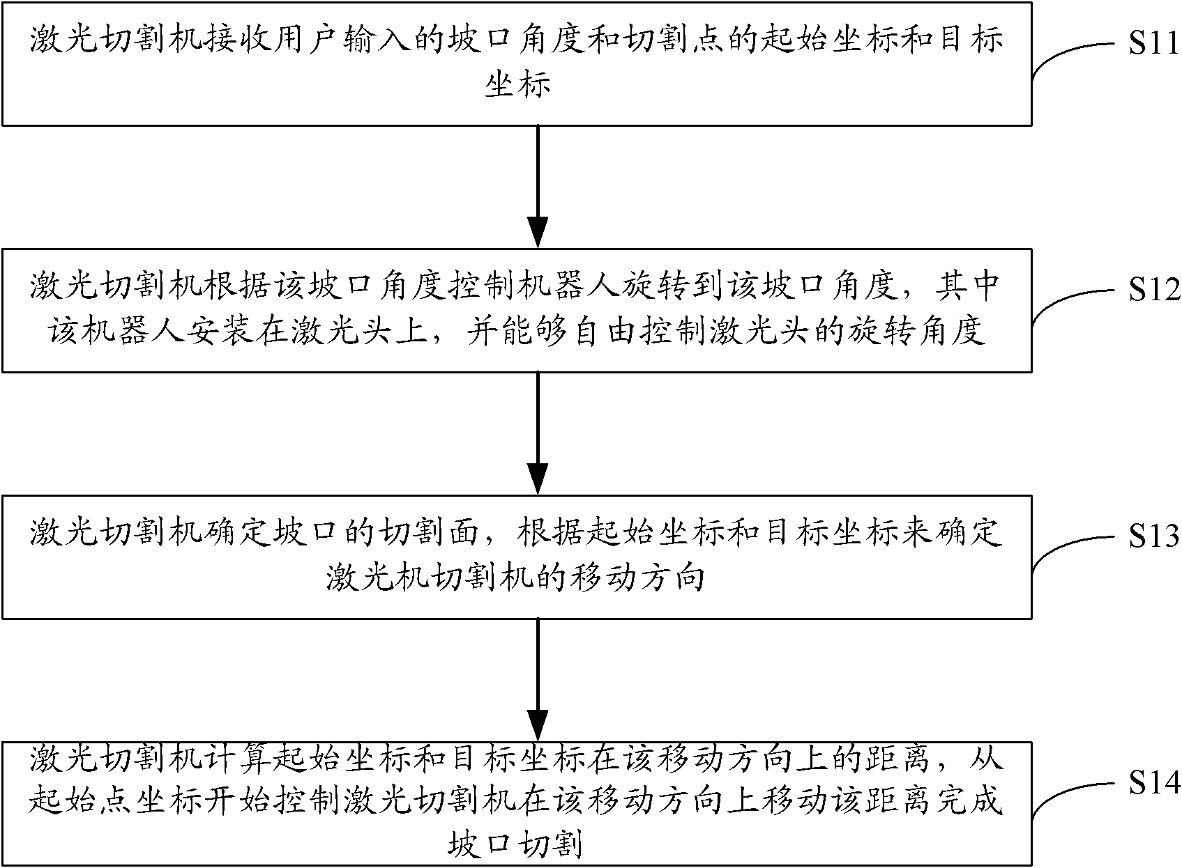
[0022] A kind of method that utilizes laser to carry out bevel cutting provided by the present invention, this method is finished by laser cutting machine, and this method is as follows figure 1 shown, including:

[0023] S11. The laser cutting machine receives the groove angle input by the user and the starting coordinates and target coordinates of the cutting point;

[0024] S12. The laser cutting machine controls the robot to rotate to the groove angle according to the groove angle, wherein the robot is installed on the laser head and can freely control the rotation angle of the laser head;

...


PUM


Abstract

The invention is applied to the field of machining, and provides a method for cutting a groove by utilizing laser and a laser cutting machine. The method comprises the following steps that the laser cutting machine receives a groove angle and starting coordinates and destination coordinates of a cutting point from a user; the laser cutting machine controls a robot to rotate to the groove angle according to the groove angle, wherein the robot is arranged on a laser head, and can freely control a rotating angle of the laser head; the laser cutting machine determines the cut surface of the groove, and determines the movement direction of the laser cutting machine according to the starting coordinates and the destination coordinates; and the laser cutting machine calculates a distance between the starting coordinates and the destination coordinates in the movement direction, and is controlled to move for the distance in the movement direction from the starting coordinates to finish cutting the groove. The technical scheme has the advantage of capability of cutting the groove.

Description

technical field [0001] The invention belongs to the field of processing, and in particular relates to a method for cutting a bevel by using a laser and a laser cutting machine. Background technique [0002] The energy released when the fiber laser beam of the laser cutting machine irradiates the surface of the steel plate melts and evaporates the blank. The laser source generally uses carbon dioxide or optical fiber (fiber) laser beams, and the laser beams are focused on a small area through optical lenses. The high concentration of energy can carry out rapid local heating, rapidly melt the billet, and realize processing by blowing off compressed gas to form fine slits. In addition, because the energy is very concentrated, only a small amount of heat is transferred to other parts of the blank, causing little or no deformation, and the laser can be used to cut blanks of complex shapes very accurately, and the cut blanks do not need to be further processed. processing. [0...

Claims


Application Information

Patent Timeline
IPC IPC(8): B23K26/38B23K26/42B23K26/70
Inventor 陆志勇毛大英刘潮润高云峰
Owner SHENZHEN HANS MP LASER TECH CO LTD
Why Eureka
Try Eureka