Superconducting cable line

A technology for superconducting cables and lines, which is applied to the installation of superconducting devices, circuits, cables, etc., and can solve the problems of performance degradation of superconducting cables 10, etc.

Active Publication Date: 2013-04-03
FURUKAWA ELECTRIC CO LTD
View PDF7 Cites 4 Cited by
  • Summary
  • Abstract
  • Description
  • Claims
  • Application Information

AI Technical Summary

Problems solved by technology

Furthermore, buckling or the like occurs in the superconducting wires constituting the superconducting conductor layer 112 and the superconducting shielding layer 114, so that the performance of the superconducting cable 10 is remarkably degraded.

Method used


Image

  • Superconducting cable line
  • Superconducting cable line
  • Superconducting cable line

Examples


Embodiment

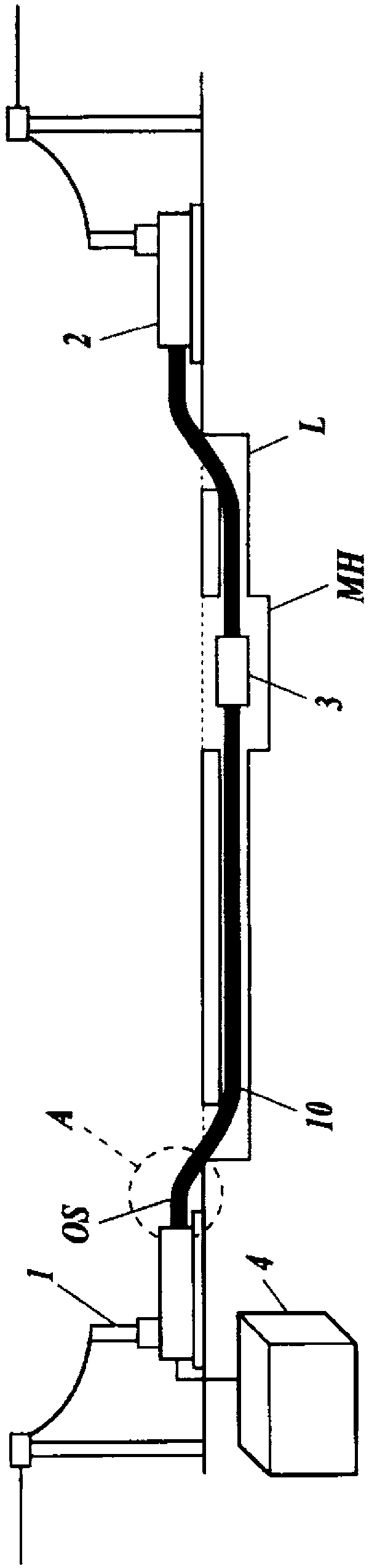
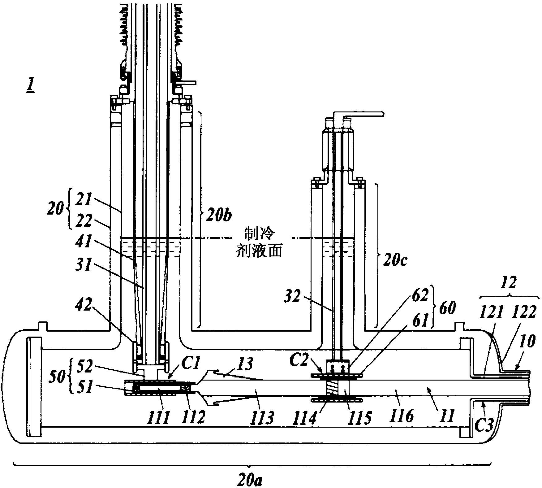
[0124] In the embodiment, one end of a superconducting cable 10 with an outer diameter of 150 mm and a cable length of 50 m is connected to the terminal connection part 1, and the other end is used as a fixed end to construct a simulation from the end of the non-moving region (equivalent to the fixed end) to the terminal. Superconducting cable line for connection 1 (see Figure 10 ). For the case where the compensation part OS was provided with different shapes (including straight laying), the thermal shrinkage when cooling from room temperature to liquid nitrogen temperature was compared with the thermal expansion when heating from liquid nitrogen temperature to room temperature. Specifically, the inside of the movable conductor connection terminal 50 of the terminal connection unit 1 was observed using an observation device using radiation such as X-rays or γ-rays, and the movement amount of the conductor plug 51 in the conductor socket 52 was measured. On the other hand, t...


PUM

PropertyMeasurementUnit
radiusaaaaaaaaaa

Abstract

In this superconducting cable line, wherein a superconducting cable is connected to terminal connecting sections or an intermediate connecting section, an offset portion where the superconducting cable is disposed in a curved manner is provided close the terminal connecting sections or the intermediate connecting section. When it is assumed that the superconducting cable can move in the offset portion, an outer tube of the superconducting cable is fixed such that a maximum amplitude portion cannot move, said maximum amplitude portion having a maximum quantity of a move of the superconducting cable due to thermal expansion and contraction of a cable core.

Description

technical field [0001] The invention relates to superconducting cable lines with terminal connections or intermediate connections. Background technique [0002] Conventionally, a superconducting cable using a superconducting wire in a superconducting state as a conductor under extremely low temperature conditions is known. Superconducting cables are expected to be able to transmit large currents with low loss, and are being developed for practical use. [0003] figure 2 An example of a superconducting cable is shown. figure 2 The shown superconducting cable 10 is a single-core type superconducting cable in which a single-core cable core 11 is accommodated in a heat insulating tube 12 . [0004] The cable core 11 is composed of a support tube 111 , a superconducting conductor layer 112 , an electrical insulation layer 113 , a superconducting shielding layer 114 , a constant conductance shielding layer 115 , a protective layer 116 and the like. The superconducting conducto...

Claims


Application Information

Patent Timeline
Patent Type & Authority Applications(China)
IPC IPC(8): H02G9/10H01B12/02H02G15/34
CPCY02E40/648H02G15/34Y02E40/60H01B12/02
Inventor 八木正史向山晋一米村德伟野村朋哉
Owner FURUKAWA ELECTRIC CO LTD
Why Eureka
Try Eureka