Buffering member, shaft coupled structure, and a uniaxial eccentric screw pump

A technology for connecting structural bodies and buffer parts, applied in the field of buffer parts, can solve problems such as failure, impact, and looseness of the driving machine, and achieve the effect of reducing operating funds

Active Publication Date: 2013-04-10
HEISHIN ENGINEERING & EQUIPMENT CO LTD
View PDF8 Cites 0 Cited by
  • Summary
  • Abstract
  • Description
  • Claims
  • Application Information

AI Technical Summary

Problems solved by technology

[0005] However, when the output shaft and the driven shaft are joined together using the above-mentioned shrink fit, there is a problem that when the output shaft and the driven shaft are separated for maintenance, etc., it is necessary to heat the joined part, requiring considerable labor, time, and dedicated equipment. Wait
In addition, there is a problem that when an external force acts in the axial direction from the driven shaft side, the external force acts directly on the output shaft, the driving machine such as the motor, etc., and may cause a failure of the driving machine, etc.
In addition, in the case of joining with a shrink fit, there is also a problem that some influence caused by heat conduction and thermal expansion may be affected from one side of the output shaft and the driven shaft to the other side.
[0006] In addition, although the countermeasure of connecting the output shaft and the driven shaft by so-called "key coupling" can also be considered, there is the following problem: simply connecting by such a connection method may cause problems at the center of the two shafts. deviation and looseness
However, even if these countermeasures are taken, there is still a problem that sufficient effects cannot be obtained and essential improvement cannot be obtained.

Method used


Image

  • Buffering member, shaft coupled structure, and a uniaxial eccentric screw pump
  • Buffering member, shaft coupled structure, and a uniaxial eccentric screw pump
  • Buffering member, shaft coupled structure, and a uniaxial eccentric screw pump

Examples


Embodiment Construction

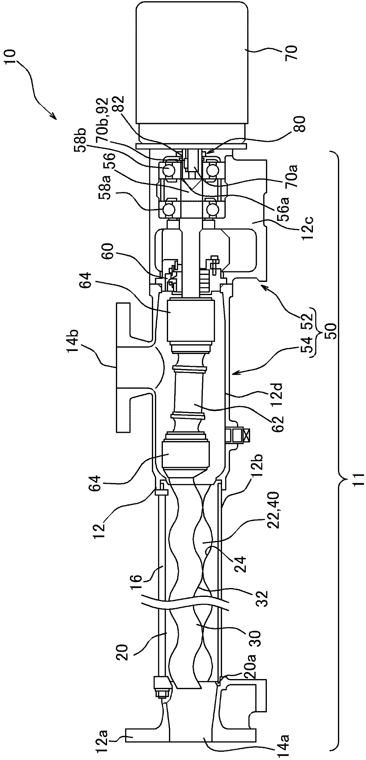
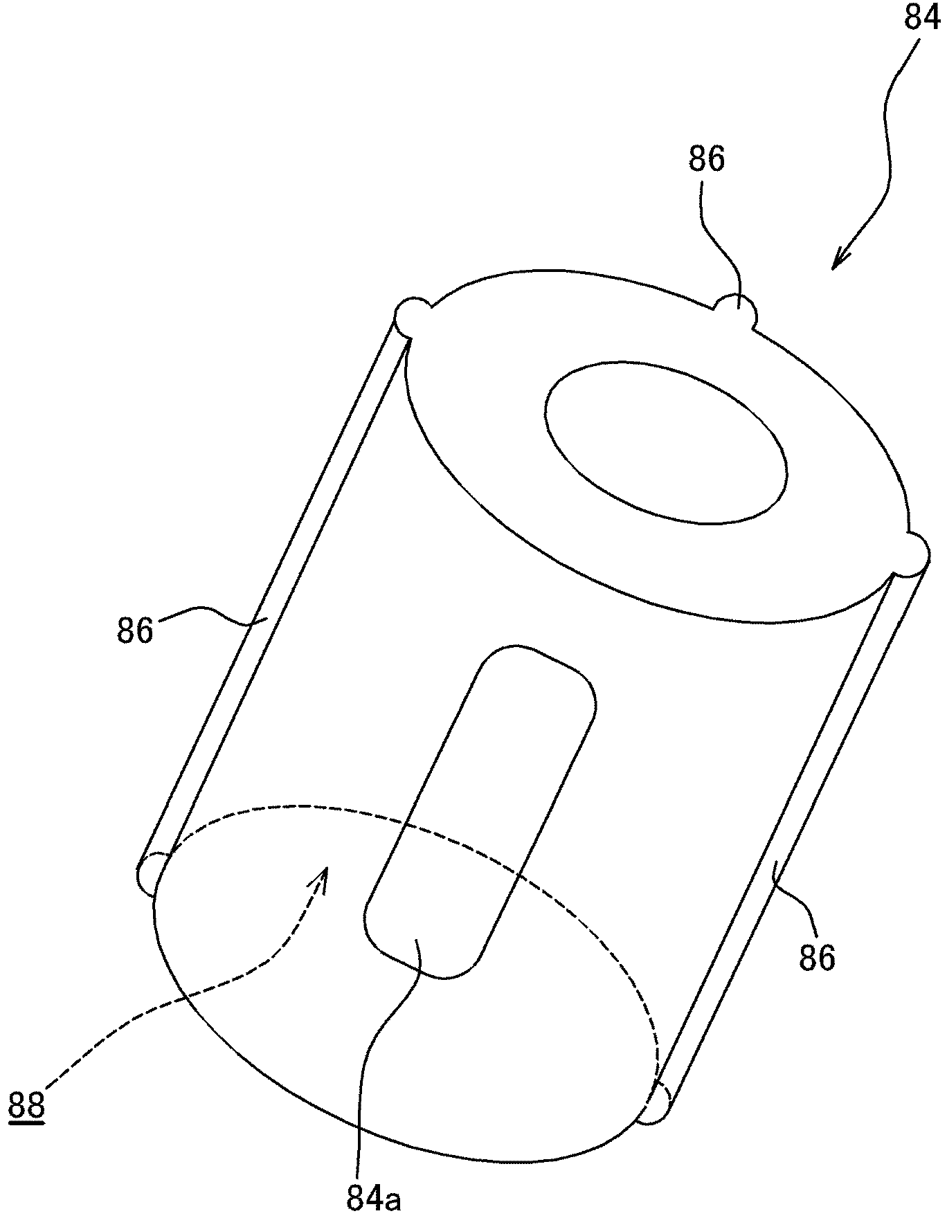
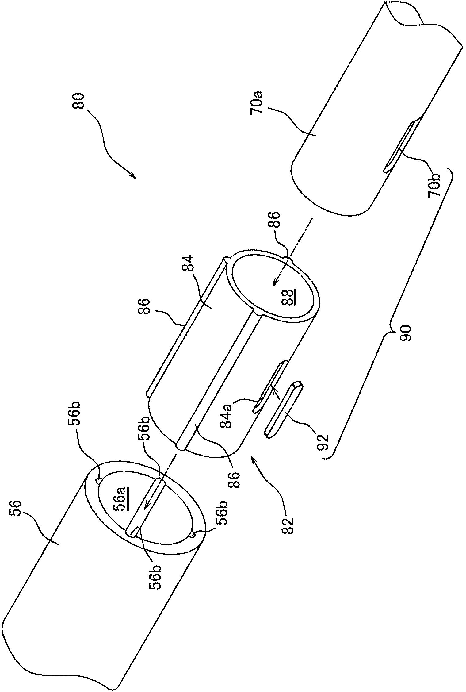
[0054] Next, the uniaxial eccentric screw pump 10 , the shaft connection structure 80 , and the buffer member 82 according to an embodiment of the present invention will be described in detail with reference to the drawings. In addition, the uniaxial eccentric screw pump 10 is characterized by a shaft connection structure 80 and a buffer member 82 . In the following description, before explaining them, the overall structure will be explained.

[0055] "Overall structure of one-axis eccentric screw pump 10"

[0056] The one-axis eccentric screw pump 10 is a so-called rotary positive displacement pump. Such as figure 1 As shown, a stator 20 , a rotor 30 , a power transmission mechanism 50 , and the like are accommodated inside the casing 12 of the one-axis eccentric screw pump 10 , and the power transmission can be transmitted from the driving machine 70 (driver) installed outside the casing 12 . dynamic action. That is, in the uniaxial eccentric screw pump 10 , the part on ...


PUM


Abstract

Disclosed is a buffering member which is capable of easily linking an output shaft and a passive shaft so as not to cause misalignment or looseness of the shaft centers, and which is capable of suppressing outside forces working directly from one of the shafts towards the other of the shafts and of suppressing the effects caused by thermal conductivity and thermal expansion; also disclosed is a uniaxial eccentric screw pump provided with said buffering member. By being interposed between an output shaft (70a) and a drive shaft (56), a buffering member (82) is capable of linking both shafts. The buffering member (82) is made from a resin, and has a tubular buffering member main body (84) and a coupling means (90). By being inserted into a buffering member insertion area (56a) disposed on the end of the drive shaft (56), the buffering member main body (84) assumes a state in which said buffering member main body (84) is fitted in and coupled with the drive shaft. Further, by inserting an output shaft (70a) into an insertion area (88) disposed on the buffering member main body (84) and engaging with a key seat (70b) a key (92) which forms a coupling means, the output shaft (70a) and the buffering member main body (84) assume a linked state.

Description

technical field [0001] The present invention relates to a buffer member, a shaft connection structure including the buffer member, and a one-axis eccentric screw pump including the shaft connection structure. shaft and the driven shaft connected to the output shaft. Background technique [0002] So far, in the one-axis eccentric screw pump disclosed in the following patent document 1, etc., when the driven shaft provided on the side of the pump body (driven machine) is connected to the output shaft of the driving machine composed of an electric motor, etc., the driven shaft is used. Joining is performed by a method called shrink fit. Joining using a shrink fit is performed by inserting one end of the output shaft and the driven shaft into the other in a heated state, and expanding or contracting the other. Engaged in this way, the two shafts can be joined together in a state where the shaft centers do not deviate and there is no looseness. [0003] patent documents [00...

Claims


Application Information

Patent Timeline
Patent Type & Authority Applications(China)
IPC IPC(8): F16D3/12F04C2/107F04C15/00F16D3/50F16F15/12
CPCF04C2/1071F04C15/0073F16D1/02F16D1/0876F16D3/02F16D3/56F16D2001/062F04C2/107F16D3/00F16D3/12F16D3/50F16F15/12
Inventor 桑山彰崇田中圭
Owner HEISHIN ENGINEERING & EQUIPMENT CO LTD
Why Eureka
Try Eureka