Steel wire mesh netting machine for coal mine anchor rod supporting

A bolt support and steel wire mesh technology, applied in the mechanical field, can solve the problems of uncontrollable tension force, affecting the overall bearing capacity, affecting aesthetics, etc.

Inactive Publication Date: 2015-01-28
山西尚科宏图防护网机技术开发有限公司
View PDF7 Cites 0 Cited by
  • Summary
  • Abstract
  • Description
  • Claims
  • Application Information

AI Technical Summary

Problems solved by technology

[0003]①The edge of the woven hexagonal mesh is curved, and the hexagonal mesh with straight mesh edges cannot be woven
[0004]②The number of twisting turns of the two mesh wires is limited by the stroke of the rack, generally only two turns
[0005]③The tension cannot be controlled when the two wires are twisted. For the woven hexagonal mesh, the tension of the wires is uneven and there is no prestress in the wires.
Affects the aesthetics of the web
Affect the overall carrying capacity of the network
[0007]⑤ Among each pair of half gears, only one half gear is connected with the spring wire barrel storing the weft thread, and the half gear also drives the spring wire barrel while twisting the net Eccentric rotation makes the machine run unstable and poor in safety
[0009]⑦This kind of net weaving mechanism can only weave thin wire mesh because a pair of half gears can only transmit a small torque, and the diameter of the mesh is generally less than 3mm
It cannot weave large-diameter mesh wire hexagonal mesh, and cannot meet the engineering needs for large-diameter hexagonal mesh
[0010] In short, the hexagonal mesh machine mechanism and weaving method currently in use cannot weave large-diameter mesh, with straight mesh edges, and mesh with good straightness and Prestressed hexagonal mesh
Thus limiting the wide application of hexagonal mesh

Method used


Image

  • Steel wire mesh netting machine for coal mine anchor rod supporting
  • Steel wire mesh netting machine for coal mine anchor rod supporting
  • Steel wire mesh netting machine for coal mine anchor rod supporting

Examples


Embodiment

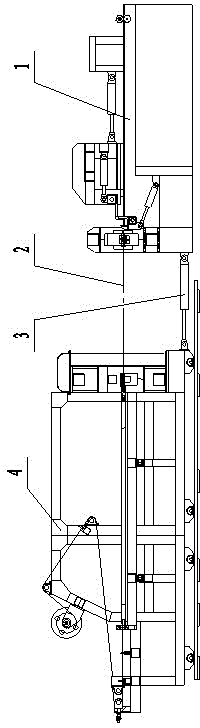
[0135] Example: figure 1 Shown, present embodiment comprises main frame 1 and follower 4, and main frame 1 is fixed on the foundation, and follower 4 moves back and forth on its own track, is connected with hydraulic cylinder 3 between two machines and pulls follower to move. All the meshes pass through the shuttle row of the main machine and the follower, and the hydraulic cylinder is used to push the follower to tension the mesh so that the mesh has tension.

[0136] The main machine is the mechanism for weaving the net, and the follower is the mechanism for unwinding and storing the mesh. Each working mechanism and each step of the network machine are automatically controlled by the PLC automatic control system.

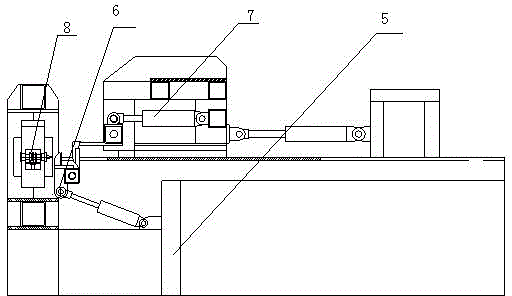
[0137] figure 2 As shown, the main frame 1 includes a main frame 5, a shuttle mechanism 7, a mesh comb mechanism 6, a net pulling mechanism 8, and a net pressing mechanism. The shuttle row mechanism 7 is arranged on the front of the net comb mechanism 6, and ...


PUM


Abstract

The invention relates to a steel wire mesh netting machine for coal mine anchor rod supporting, belonging to the field of machinery, which comprises a main machine and a following machine, wherein the main machine is fixed on a base; the following machine moves back and forth on the orbit of the following machine; the main machine and the following machine are connected through a hydraulic cylinder and the following machine is pulled to move; all meshes penetrate through the shuttle bars of the main machine and the following machine; an oil cylinder is used for pushing the flowing machine to tension the meshes so that the meshes have tensile force; the main machine comprises a main machine frame, a shuttle bar mechanism, a mesh combing mechanism and a mesh pulling mechanism; the shuttle bar mechanism is arranged in front of the mesh combing mechanism; and the mesh pulling mechanism is arranged at the back of the mesh combing mechanism. A hexagonal wire mesh with thick meshes and small mesh openings can be knitted through the machine. The diameter of the knitted mesh is 3-4.5mm, and the width of the mesh opening is 50mm.

Description

technical field [0001] The invention belongs to the field of machinery, and in particular relates to a wire mesh weaving machine for bolt support in coal mines, which is mainly used for weaving hexagonal wire mesh. Background technique [0002] Utility model patent ZL02220196.3 discloses a hexagonal mesh weaving mechanism. It adopts two staggered plates to move relative to each other, install several pairs of half gears in the opposite seams of the staggered plates, and use the rack to pull the half gears to rotate. There is a hole in each half gear, and the warp and weft threads are inserted into the holes. And the two wires are fixed on the netting cylinder, when the half gear is pulled and rotated by the rack, the two meshes are twisted mutually for two weeks, and then pulled out a certain distance by the netting cylinder. Afterwards, the staggered plates are staggered with each other, and the half gears are also staggered thereupon. At the same time, pull the mesh to m...

Claims


Application Information

Patent Timeline
Patent Type & Authority Patents(China)
IPC IPC(8): B21F27/06
Inventor 许步勤
Owner 山西尚科宏图防护网机技术开发有限公司
Why Eureka
Try Eureka