Motor stator and manufacturing method thereof

A manufacturing method and motor stator technology, applied in the manufacture of stator/rotor body, magnetic circuit shape/style/structure, magnetic circuit static parts, etc., can solve the problem of increased slot leakage reactance, large no-load stray loss, and Solve the problems of motor air gap magnetic field and other problems, achieve the effect of simple manufacturing process, increase the speed of embedding wire, and improve the performance of the motor

Active Publication Date: 2016-06-08
NINGBO YUNSHENG +2
View PDF5 Cites 0 Cited by
  • Summary
  • Abstract
  • Description
  • Claims
  • Application Information

AI Technical Summary

Problems solved by technology

[0003] Since the opening slot affects the air gap magnetic field of the motor, the no-load stray loss is large, which increases the no-load iron loss
[0004] Although the semi-closed slot is small and has little effect on the air gap magnetic field, it is more difficult for the winding, especially for the double-layer, single-layer double-layer parallel wires and the number of turns that cannot be mechanically and automatically wound at present. and inefficient
[0005] Semi-open slots and open slots have relatively large slot openings, which improve the winding insertion efficiency, but affect the air-gap magnetic field of the motor, resulting in large no-load stray losses and increased no-load iron losses
Although magnetic slot wedges can be used to reduce partial load stray losses, the slot leakage resistance increases, and there are hidden dangers of magnetic slot wedge loosening caused by vibration and wear during operation.

Method used


Image

  • Motor stator and manufacturing method thereof
  • Motor stator and manufacturing method thereof
  • Motor stator and manufacturing method thereof

Examples


Embodiment 1

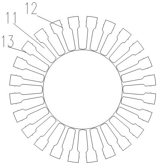
[0021] Example 1, such as figure 1 As shown in the iron core body 1 , the iron core body is provided with a strip-shaped groove 11 from the center to the circumferential direction, and the width of the strip-shaped groove is reduced near the circumference 12 and a protrusion 13 is provided.

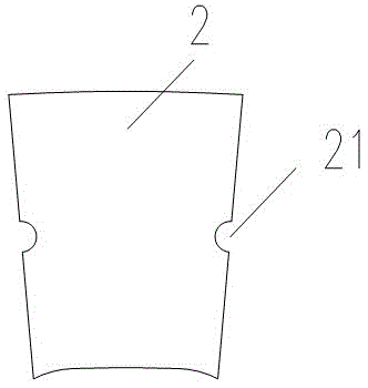
[0022] Such as figure 2 As shown, the core sealing piece 2 is provided with a groove 21 corresponding to the protrusion 13 .

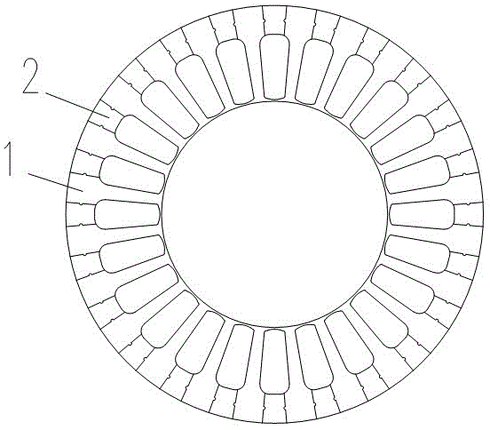
[0023] Such as image 3 As shown, the iron core main body 1 is combined with the iron core sealing piece 2 to form an iron core, and the iron core sealing piece 2 is inserted into the vicinity of the circumference 12 of the strip groove 11 of the iron core main body 1, so that the groove 21 cooperates with the protrusion 13 and the The iron core closing piece 2 is limited on the iron core main body 1 .

[0024] The above-mentioned multi-piece iron core main body 1 and the iron core sealing piece 2 are superimposed to form the motor stator.

Embodiment 2

[0025] Embodiment 2, similar to Embodiment 1, the main difference is that the buckle between the iron core body and the iron core sealing piece changes, and the protrusion on the iron core body becomes a groove, and the corresponding iron core seals The grooves of the sheet are changed to protrusions, but are not shown in the figure because they are easy to understand.

[0026] The above motor stator can be prepared according to the following method: 1) Select a square iron sheet 3, punch out the iron core main body 1 and the iron core sealing sheet 2 on the iron sheet 3 according to the shape of the iron core main body 1 and the iron core sealing sheet 2, Figure 4 According to the layout diagram of the shape of the iron core main body 1 and the iron core sealing piece 2 before punching, Figure 5 In order to punch out the iron core main body 1 and the remaining iron sheet of the iron core sealing piece 2; 2) Insert the iron core sealing piece 2 into the bar-shaped groove of ...


PUM


Abstract

The invention discloses a motor stator, which comprises a plurality of laminated iron cores provided with winding grooves. The motor stator is characterized in that the iron cores comprise iron core main bodies and iron core enclosing sheets, wherein the iron core main bodies are provided with strip-shaped grooves from the centers to the circumferential direction; the widths of the strip-shaped grooves are reduced at positions close to the circumferences; and the iron core enclosing sheets are inserted into positions, close to the circumferences, of the strip-shaped grooves of the iron core main bodies, and are limited on the iron core main bodies. Due to the adoption of the motor stator, convenience can be brought to winding, and the motor performance can be improved. The invention correspondingly provides a manufacturing method of the motor stator, and according to the method, the motor stator is easy to manufacture.

Description

technical field [0001] The invention relates to a stator for an electrical machine and a corresponding manufacturing method thereof. Background technique [0002] Existing motor stators all have slots, and the slot shapes generally have three types: semi-closed slots, semi-open slots, and open slots. [0003] Since the open slot affects the air gap magnetic field of the motor, the no-load stray loss is large, and the no-load iron loss increases. [0004] Although the semi-closed slot is small and has little effect on the air gap magnetic field, it is more difficult for the winding, especially for the double-layer, single-layer double-layer parallel wires and the number of turns that cannot be mechanically and automatically wound at present. And it's inefficient. [0005] Half-open slots and open slots have relatively large slot openings, which improve the winding insertion efficiency, but affect the air-gap magnetic field of the motor, resulting in large no-load stray loss...

Claims


Application Information

Patent Timeline
Patent Type & Authority Patents(China)
IPC IPC(8): H02K1/12H02K15/02
Inventor 黄利军陆海成
Owner NINGBO YUNSHENG
Why Eureka
Try Eureka