Straight-flow shut-off valve sealed with elastic valve seat under fluid pressure

A technology of elastic valve seat and fluid pressure, applied in the direction of lift valve, valve details, valve device, etc., can solve the problems of space, position, location, etc., the operation is not very convenient, and can not be implemented, etc. , The effect of small operation force and convenient installation

Inactive Publication Date: 2013-05-08
戴学祥
View PDF6 Cites 4 Cited by
  • Summary
  • Abstract
  • Description
  • Claims
  • Application Information

AI Technical Summary

Problems solved by technology

The advantages are obvious, but the disadvantage is that it is not very convenient to operate, and it is greatly affected by space, location, and location. Especially in the aspect of production automation control, it is more difficult to operate the valve as an electric device, or it cannot be implemented. Therefore, to achieve the purpose of reducing fluid resistance with this valve, it is still very limited, and the use of it cannot achieve satisfactory results.

Method used


Image

  • Straight-flow shut-off valve sealed with elastic valve seat under fluid pressure
  • Straight-flow shut-off valve sealed with elastic valve seat under fluid pressure
  • Straight-flow shut-off valve sealed with elastic valve seat under fluid pressure

Examples


Embodiment 1

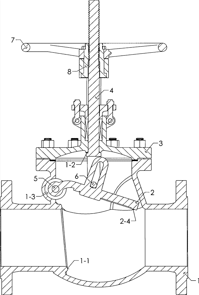
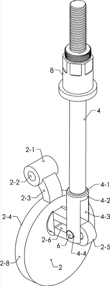
[0025] Example 1 as figure 1 and figure 2 As shown, the sealing body of the valve flap (2) is a circular platform (2-8), and the upper end of the peripheral surface has an additional cylindrical support body (2-1) formed along the center to both sides, and the support body (2-1) 1) The rib plate (2-3) and the two are connected, and one end is movably supported in the semicircular annular groove (1-3) protruding outward from the upper part of the valve body (1), and the pin shaft (5) passes through the valve The shaft hole on the body and the hole (2-2) on the support body (2-1) are connected to each other.

[0026] One side of the round table (2-8) on the valve disc (2) is provided with a connecting body (2-5) protruding to one side at the upper part of the center circle, and the groove in the valve stem (4) big head (4-2) The port (4-3) cooperates with the two planes of the connecting body (2-5), wherein the chute (2-6) and the pin hole (4-4) placed at the end of the valv...

Embodiment 2

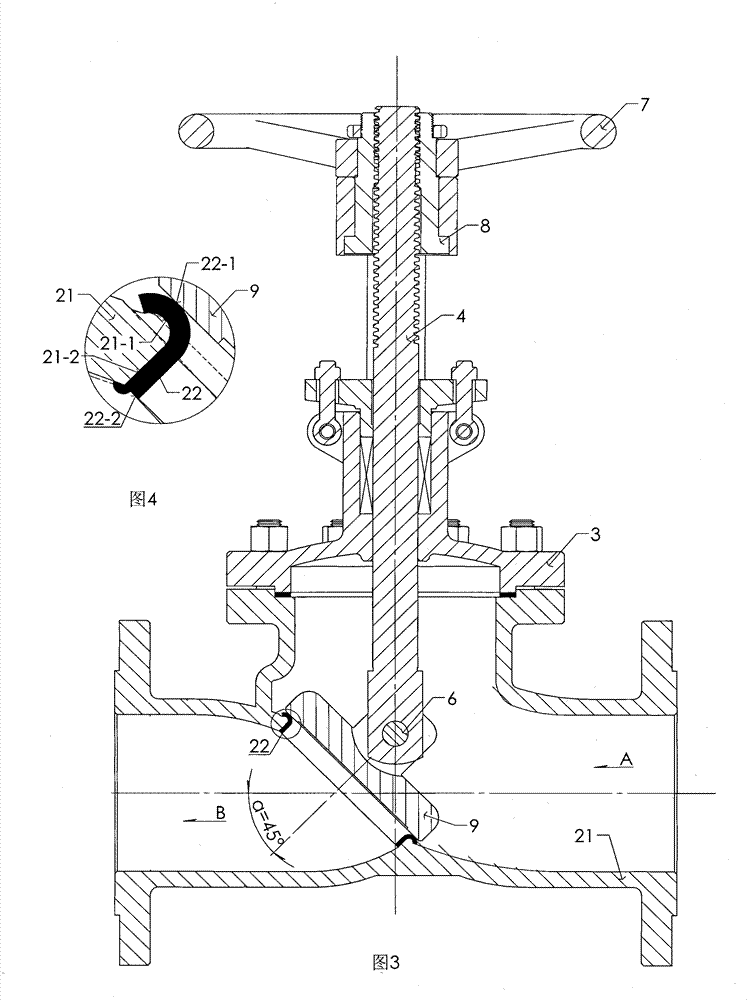
[0029] Example 2 as image 3 and Figure 4 Shown, the angle a=45 ° of valve body (21) inlet runner (A) and outlet runner (B).

[0030] The circular arc of the sealing end (22-1) of the elastic valve seat (22) is consistent with the circular arc (21-1) of the valve body (21), and the outer circle is consistent with the flow channel hole (21) in the valve body (21). -2) Cooperate.

[0031] The circular arc of the sealing end (22-1) of the elastic valve seat (22) is consistent with the circular arc (21-1) in the valve body (21), and the outer circle is consistent with the flow channel hole (21) in the valve body (21). -2) Cooperate, the end face (22-2) of the elastic valve seat (22) is integrated with the joint of the valve body (21-3) by welding.

Embodiment 3

[0032] Example 3 as Figure 5 and Figure 6 Shown, the angle a=45 ° of the flange (31-3) of valve body (31) outlet channel (B) and the flange (32-3) of bonnet (32) inlet channel (A).

[0033] The arc of the sealing end (35-1) of the elastic valve seat (35) is consistent with the arc (31-1) of the valve body (31), and the lower gasket (34) is placed in the groove of the valve body (31) In (31-2), the lower surface of the outer circle of the lower gasket (34) is in contact with and sealed with the lower plane of the outer circle of the elastic valve seat (35), and one side of the upper gasket (33) is in contact with the center of the valve cover (32). The flat surface (32-1) of the boss is in contact with and sealed, and the other side is in contact with and sealed with the upper plane of the outer circle of the elastic valve seat (35).


PUM


Abstract

The invention relates to a straight-flow shut-off valve which is sealed with an elastic valve seat under fluid pressure. According to the straight-flow shut-off valve, a support body which is arranged on a circular table of a valve flap additionally is connected with the valve flap and the circular table by a rib plate, and one end of the support body is supported in an annular groove which is bulged outwards out of the upper part of a valve body; a pin shaft is connected with a hole in the support body by a shaft hole of the valve body; a connecting body which extends out of one side is arranged at the position which is close to the upper part of a center circle on one side of a sealing body on the valve flap; a notch in the end of a valve rod is matched with two planes of the connecting body, and a straight notch is connected with a pin arranged in a pin hole in the tail end of the valve rod; an angle alpha of an inlet flow channel A and an outlet flow channel B of a valve body is 45 degrees; the circular arcs of the sealing ends of elastic valve seats are consistent with those of the valve bodies; the excircle is matched with a flow channel hole in the valve body; and upper and lower planes outside the elastic valve seat are hermetically connected with a lower sealing gasket in the valve body and an upper sealing gasket in a valve cover respectively.

Description

technical field [0001] The invention belongs to valves, in particular to a direct-flow shut-off valve utilizing fluid pressure and sealing with an elastic valve seat. Background technique [0002] There are basically five categories of general-purpose valves, which are sorted by usage: 1. Gate valves, 2. Globe valves, 3. Check valves, 4. Ball valves, 5. Butterfly valves. Among them, ball valves and butterfly valves are valves with rapid technological development in recent years, and there are many new designs. Therefore, the latter two types of valves have made rapid progress, made great contributions to the market, and their demand is further increasing. The widely used gate valves and globe valves have basically not changed much, especially the globe valves, which still stay in the long historical stage of the last century. [0003] Globe valves for petroleum and petrochemical industries are usually divided into two categories, one is vertically installed globe valves, an...

Claims


Application Information

Patent Timeline
Patent Type & Authority Applications(China)
IPC IPC(8): F16K1/18F16K27/02F16K1/42
Inventor 戴学祥
Owner 戴学祥
Why Eureka
Try Eureka