Screw and vertex combined slurry pump

A mud pump and vortex technology, which is applied in the field of construction of check dams, can solve the problems of limited solid particle size, difficult to guarantee personal safety, uncontrollable mud concentration, etc. Efficiency, simple structure effect

Inactive Publication Date: 2014-01-22
陕西省水土保持局
View PDF6 Cites 3 Cited by
  • Summary
  • Abstract
  • Description
  • Claims
  • Application Information

AI Technical Summary

Problems solved by technology

However, there are still many deficiencies in the water drop method: (1) In order to meet the gradient of input mud for filling and mud making requirements, the position of the soil field should be higher than the filling dam surface by about 10m, which limits the choice of dam site; (2) During the construction process, the mud concentration cannot be controlled, and the dam body often does not meet the requirements of a homogeneous dam; (3) Landslides and other geological disasters are easily induced near the mud channel during the process of hydraulically flushing soil materials to make mud; (4) Construction During the process, construction workers need to stand on the ditch slope to dig soil. The working conditions are poor, the labor intensity is high, and personal safety is difficult to guarantee.
The survey results show that the sludge pumps, screw pumps and slurry pumps currently used for mud transportation are either limited in mud concentration or the size of solid particles allowed to pass through, which cannot fully meet the requirements of mud pump damming on the transfer pump. Requirements, it is necessary to develop a new type of mud delivery pump in order to promote the development and application of mud pump damming technology

Method used


Image

  • Screw and vertex combined slurry pump
  • Screw and vertex combined slurry pump
  • Screw and vertex combined slurry pump

Examples


Embodiment Construction

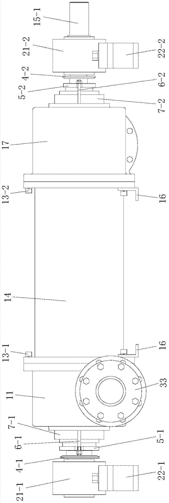
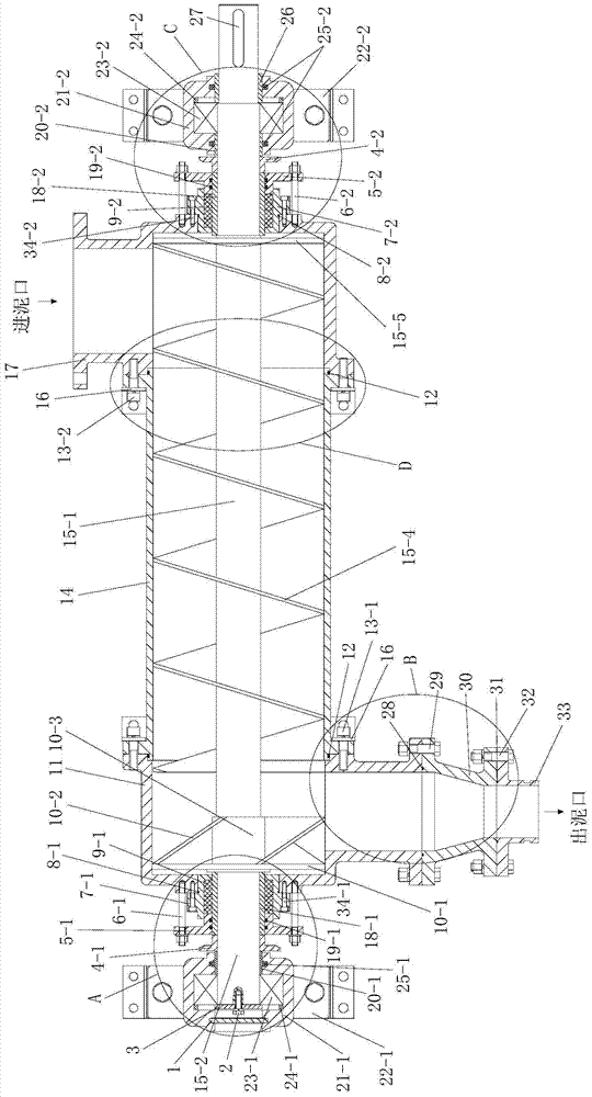
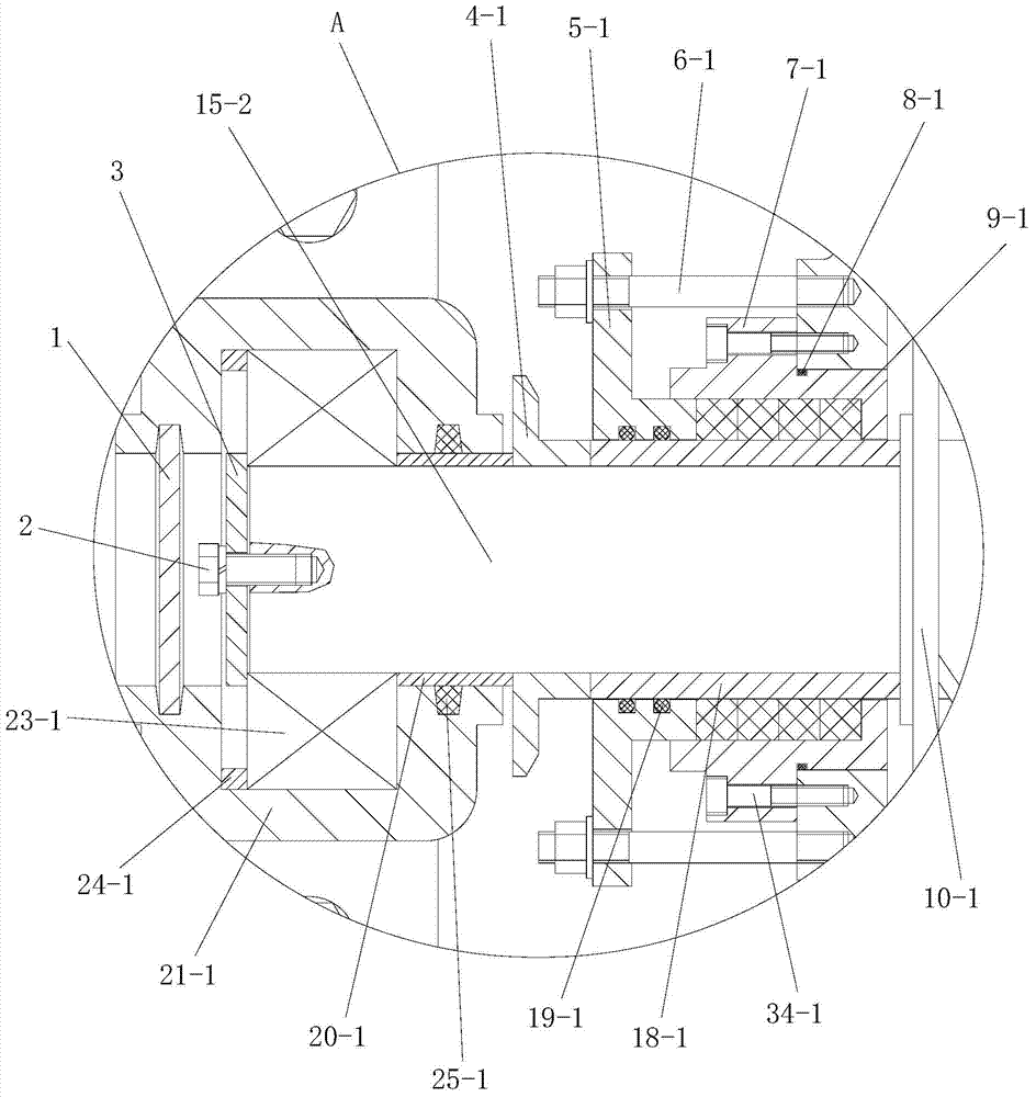
[0037] Such as figure 1 , figure 2 , Figure 8 and Figure 9 As shown, the present invention includes a cylinder body 14 and a pump shaft. The cylinder body 14 is cylindrical and has connecting flanges at both ends. The pump shaft passes through the cylinder body 14 in the axial direction and both ends are located in the cylinder body. Outside the body 14, one end of the cylinder body 14 is sealed and fixed with a casing 11, and the other end of the cylinder body 14 is sealed and fixed with a mud inlet joint 17, and the pump shaft is coaxially arranged and fixedly connected with the first pump shaft 15-2 and the second pump shaft 15-1, the outer end of the first pump shaft 15-2 passes through the casing 11, and the outer end of the second pump shaft 15-1 passes through the mud inlet joint 17. A helical blade 15-4 is installed on the second pump shaft 15-1 located in the cylinder body 14 and the mud inlet joint 17, and the cylinder body 14, the second pump shaft 15-1 and th...


PUM


Abstract

The invention discloses a screw and vortex combined slurry pump. The screw and vortex combined slurry pump comprises a cylinder body and pump shafts; the pump shafts penetrate the cylinder body along the axial direction and two ends of the pump shafts are arranged outside the cylinder body; a casing is fixed at one end of the cylinder body; a slurry inlet connector is fixed at the other end of the cylinder body; the pump shafts are formed by a first pump shaft and a second pump shaft; a screw blade is installed on the second pump shaft; a second seal device and a second supporting device are arranged on the second pump shaft and outside the slurry inlet connector; a hub is installed on the first pump shaft; a vortex blade and a first slurry blocking disc are installed on the hub; the screw direction of the vortex blade and the screw direction of the screw blade are opposite; the first slurry blocking disc is connected with the vortex blade; a first seal device and a first supporting device are arranged on the first pump shaft and outside the casing; a slurry outlet of the casing is vertical to the cylinder body; a transitional connector which is connected with a slurry outlet connector is connected to the end portion of the casing. The screw and vortex combined slurry pump solves the problem of conveying high concentration and high flow slurry which contains large hardness particles and long fibrous matters.

Description

technical field [0001] The invention belongs to the technical field of check dam construction technology, and in particular relates to a spiral and vortex composite mud pump. Background technique [0002] At present, the most common construction methods of check dams are rolling method and water drop method. Compared with the rolling method of dam construction, the water drop method of dam construction saves the process of soil loading, soil transportation and rolling, and has the advantages of compact dam body, simple construction, easy to master, labor and machinery saving, high work efficiency and low cost It is especially suitable for areas such as drought and little rain, poverty, inconvenient transportation, and difficult mechanical construction. However, there are still many deficiencies in the water drop method: (1) In order to meet the gradient of input mud for filling and mud making requirements, the position of the soil field should be higher than the filling dam...

Claims


Application Information

Patent Timeline
Patent Type & Authority Applications(China)
IPC IPC(8): F04D7/04F04D29/10F04D29/04F04D29/42
Inventor 张武俊杨西民何建民张岗虎梁斌肖继明杨长林侯书铭党新选梁书平朱首军杜涛
Owner 陕西省水土保持局
Why Eureka
Try Eureka