Optical Line Terminal and Optical Network Unit

A technology for optical line terminals and optical network units, which is applied in the direction of electrical components, multiplexing system selection devices, selection devices, etc., and can solve the problem of optical network units not having capabilities, signal crosstalk, and affecting receivers in optical line terminals Reception quality etc.

Active Publication Date: 2017-04-12
ALCATEL LUCENT SHANGHAI BELL CO LTD
View PDF6 Cites 0 Cited by
  • Summary
  • Abstract
  • Description
  • Claims
  • Application Information

AI Technical Summary

Problems solved by technology

[0006] 1. The optical network unit must be able to automatically select and match the wavelength of the tunable laser, otherwise the plug-and-play function of the optical network unit cannot be realized
In the current system, the optical network unit does not have such a capability
[0007] 2. Since the four uplink wavelengths will be multiplexed by the optical splitter, the drift of the uplink wavelength of the tunable laser in the optical network unit will cause crosstalk between signals, so if the drift cannot be eliminated in time, the communication quality will be affected
[0008] 3. The drift of the upstream wavelength will cause the upstream wavelength to deviate from the peak transmission wavelength of the receiving array waveguide grating in the optical line terminal, which will reduce the optical power and affect the receiving quality of the receiver in the optical line terminal
However, in the prior art, it is impossible to know how much the wavelength of the tunable laser deviates from the peak transmission wavelength of the arrayed waveguide grating, and it is also impossible to automatically and timely correct the deviation back

Method used


Image

  • Optical Line Terminal and Optical Network Unit
  • Optical Line Terminal and Optical Network Unit
  • Optical Line Terminal and Optical Network Unit

Examples


Embodiment Construction

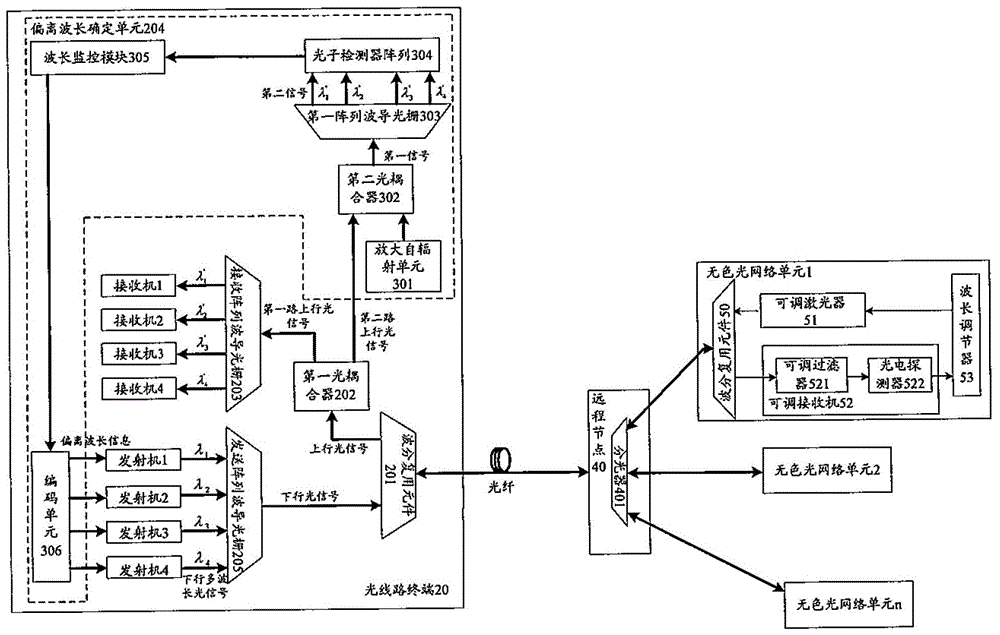
[0035] figure 2 A schematic diagram of a system for remotely controlling the wavelength of a tunable laser in an optical network unit according to an embodiment of the present invention is shown. Among them, 4XG-PON is stacked by using 4 pairs of wavelengths.

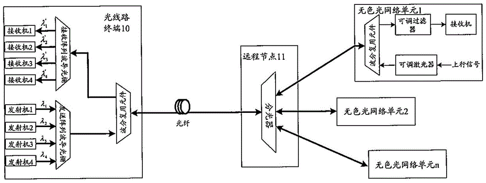
[0036] Such as figure 2 As shown, the OLT 20 is connected to multiple colorless ONUs 1 . . . n through a 1:n optical splitter 401 in the remote node 40 . A structural block diagram of the colorless optical network unit 1 is only schematically shown here. The structures of other colorless optical network units 2 to n are the same as or similar to the structure of colorless optical network unit 1 .

[0037] The optical line terminal 20 includes a wavelength division multiplexing element 201 and a first optical coupler 202 . The first optical coupler receives an uplink optical signal from the colorless optical network unit through the wavelength division multiplexing element 201 . Then, the first optical coupler 202...


PUM


Abstract

The invention provides an optical line terminal and an optical network unit. The optical line terminal of the invention comprises a deviation wavelength determination unit. The deviation wavelength determination unit is used for obtaining a second channel of uplink optical signals and determining whether the wavelength of the second channel of uplink optical signals is deviated with respect to peak transmission wavelength in the characteristic frequency spectrum of receiving arrayed waveguide grating, and determining deviation wavelength information if the wavelength of the second channel of uplink optical signals is deviated with respect to the peak transmission wavelength, and encoding the deviation wavelength information to downlink multi-wavelength optical signals. The optical network unit of the invention can adjust the wavelength of optical signals of a tunable laser according to received deviation wavelength information. By means of the optical line terminal and the optical network unit of the invention, the wavelength of the tunable laser of the optical network unit can be controlled remotely at the optical line terminal. The optical line terminal and the optical network unit of the invention are advantageous in structural simplicity, easiness in implementation and low cost.

Description

technical field [0001] The present invention relates to time-division wavelength-division multiplexing passive optical network, in particular to remotely controlling the wavelength of an adjustable laser in an optical network unit in the field of time-division wavelength-division multiplexing passive optical network, and to the design of an optical line terminal and an optical network unit . Background technique [0002] With the emergence of a large number of new advanced multimedia applications, such as the deployment of services such as 3D TV, telemedicine services, online games, and interactive video e-learning, the demand for network bandwidth carrying these applications has greatly increased. Next Generation Passive Optical Network (NG-PON2, Next Generation Passive Optical Network), has become ITU-T (Telecommunication Standardization Sector of the International Telecommunications Union, International Telecommunication Union Telecommunication Standardization Section) an...

Claims


Application Information

Patent Timeline
Patent Type & Authority Patents(China)
IPC IPC(8): H04J14/02H04Q11/00
Inventor 昌庆江高震森
Owner ALCATEL LUCENT SHANGHAI BELL CO LTD
Why Eureka
Try Eureka