Horizontal water flow vertical mud discharging sedimentation and separation device

A sedimentation separation and vertical discharge technology, applied in the sedimentation tank and other directions, can solve the problems of the complex structure of the sedimentation separation device, the sediment is easy to accumulate on the slope, and the mud discharge port is easy to block, so as to achieve the rapid and effective sedimentation effect and solve the deformation of the inclined plate. Or collapse, avoid the effect of short flow of water

Active Publication Date: 2014-03-26
ZHEJIANG DEAN TECH
View PDF7 Cites 6 Cited by
  • Summary
  • Abstract
  • Description
  • Claims
  • Application Information

AI Technical Summary

Problems solved by technology

[0004] The above-mentioned horizontal tube sedimentation and separation device partly improves the problem that the water flow and the direction of solid precipitation are easily disturbed, but the structure of the sedimentation and separation device is relatively complicated, and it also has high requirements for on-site installation, which limits its practicability; on the other hand, when the suspension When the types and sizes of the objects are relatively complicated, especially the large-sized suspended objects are easy to block the sludge outlet, and the sediment is easy to deposit on the inclined sludge discharge slide, blocking the sludge discharge channel; when the sedimentation is serious, it exceeds the bearing load of the horizontal pipe will cause the device to collapse

Method used


Image

  • Horizontal water flow vertical mud discharging sedimentation and separation device
  • Horizontal water flow vertical mud discharging sedimentation and separation device
  • Horizontal water flow vertical mud discharging sedimentation and separation device

Examples


Embodiment 1

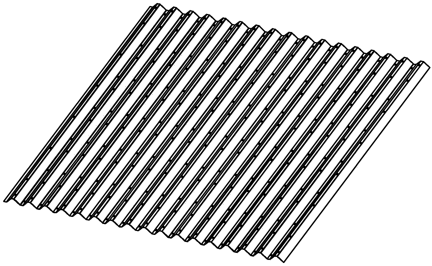
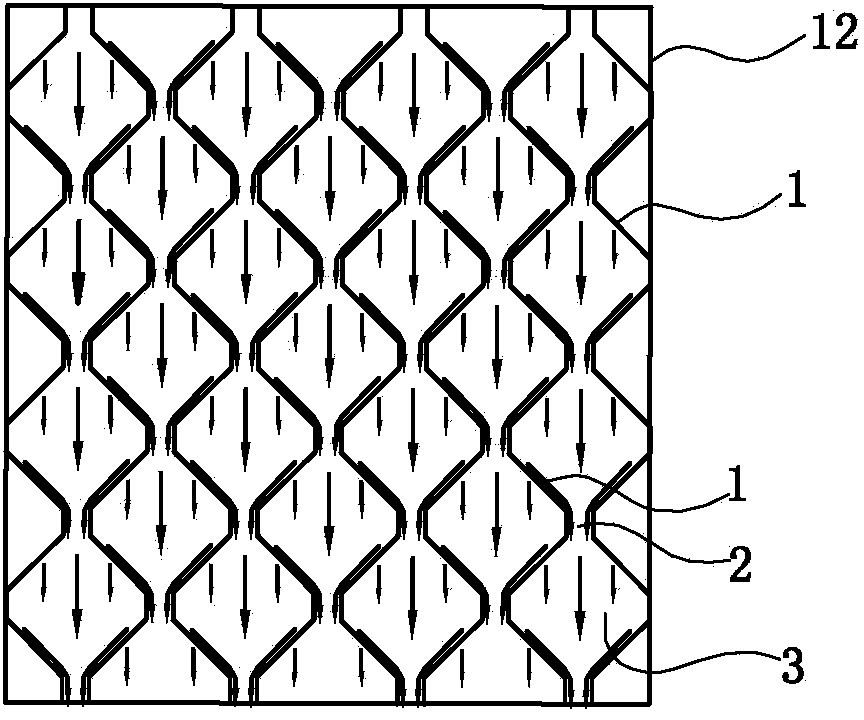
[0036] Such as Figure 1 to Figure 5 As shown, the horizontal flow vertical sludge discharge sedimentation separation device is installed in the sedimentation tank 12, which includes:

[0037] There are multiple corrugated plates 1, and these corrugated plates are arranged vertically relative to the horizontal plane, and the cross-section of the corrugated plates has a trapezoidal wave structure. The trapezoidal wave in this embodiment is an isosceles trapezoid, and the included angle α between the two waists and the corresponding valley bottom is 45°, and the width of the valley bottom is 1 cm. The width of the valley bottom can also select other sizes according to needs, usually Between 0.5 and 2 cm. The length of the two waists is 3 centimeters; the length of the waist can also be selected for other sizes as required, such as 2 to 3.5 centimeters.

[0038]In this embodiment, the surface of each corrugated pipe has a hydrophobic layer, thereby effectively reducing the resi...

Embodiment 2

[0045] Such as Figure 6 to Figure 8 As shown, the horizontal flow vertical sludge discharge and sedimentation separation device includes:

[0046] There are multiple corrugated plates 1, and these corrugated plates are arranged vertically relative to the horizontal plane, and the cross-section of the corrugated plates has a trapezoidal wave structure. The trapezoidal wave in this embodiment is an isosceles trapezoid, and the included angle α between the two waists and the corresponding valley bottom is 45°, and the width of the valley bottom is 1 cm. The width of the valley bottom can also select other sizes according to needs, usually Between 0.5 and 2 cm. The length of the two waists is 3 centimeters; the length of the waist can also be selected for other sizes as required, such as 2 to 3.5 centimeters.

[0047] In this embodiment, the surface of each corrugated pipe has a hydrophobic layer, thereby effectively reducing the resistance of the surface of the corrugated plat...

Embodiment 3

[0053] as above Figure 9 to Figure 13 As shown, the waveform of the cross section of the corrugated plate 14 in this embodiment is a triangular wave, such as Figure 10 As shown, a plurality of clamping holes 15 are arranged at intervals at sharp corners of the corrugated plate. In this embodiment, the distance between adjacent locking holes is 9 cm.

[0054] In the gap between adjacent corrugated plates 14, a plurality of partitions 16 are arranged at intervals, and these partitions run longitudinally between adjacent corrugated plates; The space between them is suitable, and it is also a zigzag structure to facilitate the positioning of the partition and the corrugated board when they are assembled; the rest of the partition is a linear plate structure, and the width of this partition is larger than that of the adjacent partition. The minimum distance between the plates is smaller than the maximum distance between adjacent partitions, that is, part of the edge of the part...


PUM


Abstract

The invention relates to a horizontal water flow vertical mud discharging sedimentation and separation device, which is characterized by comprising a plurality of corrugated boards mounted in a sedimentation tank; all the corrugated boards are vertically arranged relative to the horizontal plane; adjacent corrugated boards are symmetrically arranged and spaced; the minimum distances between the adjacent corrugated boards are mud discharging channels. Compared with the prior art, the horizontal water flow vertical mud discharging sedimentation and separation device reserves the advantage that a water flow is vertical to the mud discharging direction of sediment and does not interfere in the sediment, avoids the disturbance of a horizontal water flow to the sediment, prevents sinking mud from suspending, meanwhile, optimizes a mud discharging manner and adopts the vertical mud discharging channels; after a water flow horizontally flows through the water flowing channels, suspended matters bump into the side frames of the water flowing channels, quickly deposit, and slide downwards along the side frames to the mud discharging channels, and directly deposit at the bottom of the sedimentation tank; an oblique board bears nothing, so that the load bearing problem of the oblique board, caused by overweight sediment, is solved.

Description

technical field [0001] The invention relates to the technical field of water treatment, and specifically refers to a horizontal flow vertical mud discharge sedimentation separation device for solid and liquid separation with supporting sedimentation facilities. Background technique [0002] The sedimentation and separation device is the basic unit in water treatment technology, and the research and development of high-efficiency sedimentation device has always been the focus of attention of those skilled in the art. At present, the sedimentation and separation device with inclined tube or inclined plate structure widely used in the sedimentation tank can effectively increase the sedimentation area and improve the sedimentation effect, but the direction of water flow is parallel to the direction of sedimentation, and the liquid and solid are prone to interference, which affects the sedimentation effect. ; It is easy to accumulate mud, block the inclined pipe or inclined plate...

Claims


Application Information

Patent Timeline
Patent Type & Authority Applications(China)
IPC IPC(8): B01D21/02
Inventor 俞建德
Owner ZHEJIANG DEAN TECH
Why Eureka
Try Eureka