Exhaust system and control method for reducing exhaust back pressure

A technology of exhaust back pressure and exhaust system, applied in the direction of electronic control of exhaust treatment device, exhaust treatment, exhaust device, etc., can solve problems such as affecting engine performance, increasing exhaust back pressure, and affecting engine performance. , to improve power and economy, reduce exhaust back pressure, and facilitate performance verification.

Inactive Publication Date: 2014-04-23
ZHEJIANG GEELY HLDG GRP CO LTD +1
View PDF5 Cites 5 Cited by
  • Summary
  • Abstract
  • Description
  • Claims
  • Application Information

AI Technical Summary

Problems solved by technology

Existing exhaust systems generally have a fixed structure, and the exhaust back pressure increases with the increase of the engine speed. The commonly used operating range of the engine is between 800-2800rpm. At this time, the maximum back pressure of the exhaust system is not greater than 21Kpa, less than 30% of maximum exhaust back pressure, limited effect on engine performance
However, when the vehicle is accelerating at a low gear or driving at a high speed, the engine is in a high-speed operating condition, and the exhaust back pressure increases significantly, which affects the performance of the engine.

Method used


Image

  • Exhaust system and control method for reducing exhaust back pressure
  • Exhaust system and control method for reducing exhaust back pressure
  • Exhaust system and control method for reducing exhaust back pressure

Examples


Embodiment Construction

[0024] The present invention will be further described below in conjunction with the embodiments shown in the accompanying drawings.

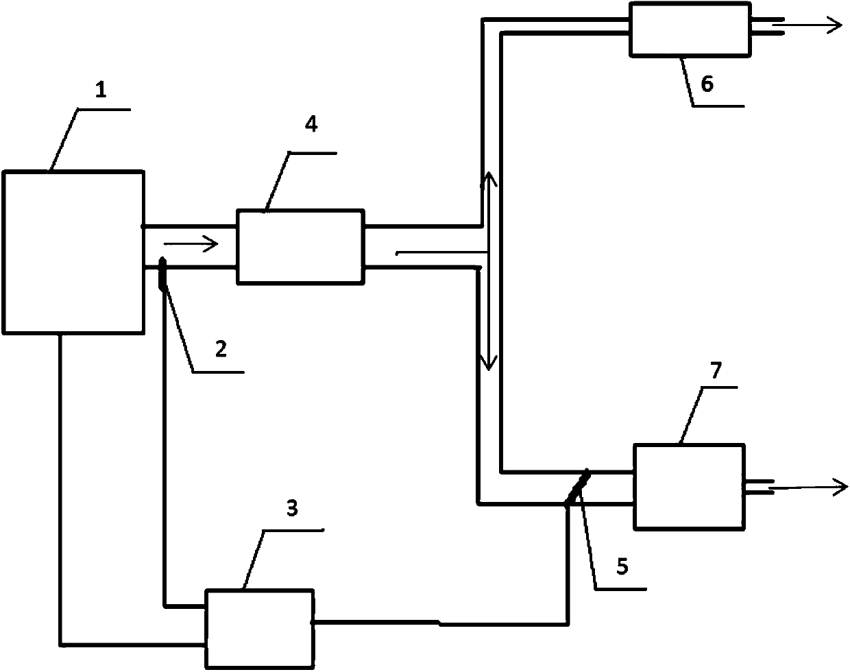
[0025] Such as figure 1 As shown, in the first embodiment, the present invention provides an exhaust system for reducing exhaust back pressure, including an exhaust manifold, an exhaust back pressure sensor 2 installed at the front end of the exhaust manifold, The front muffler 4, the first rear muffler 6, the second rear muffler 7 and the controller 5 are connected by the manifold.

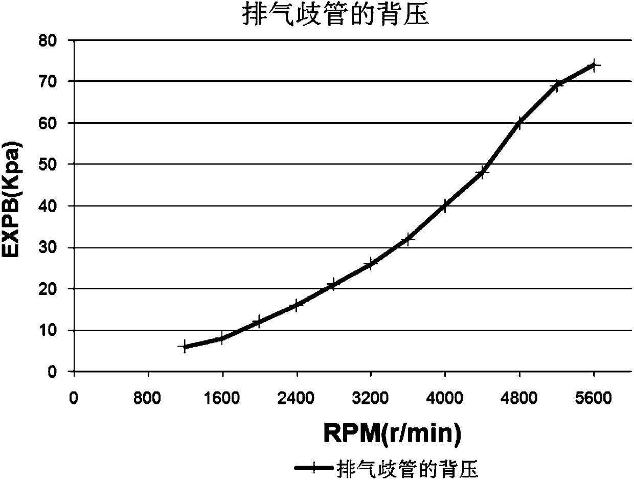
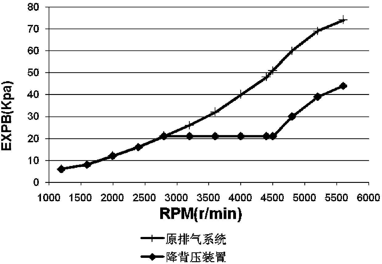
[0026] The exhaust manifold is installed at the rear of the engine assembly 1, and the exhaust back pressure sensor 2 is located at the front end of the exhaust manifold to measure the exhaust back pressure of the engine in real time. Mounting threads are reserved for the back pressure sensor 2, and the exhaust back pressure sensor 2 is directly installed on the exhaust manifold.

[0027] The front muffler 4 belongs to the resistive structure, and it is used as ...


PUM


Abstract

Disclosed are an exhaust system and a control method for reducing the exhaust back pressure. The exhaust system comprises an exhaust manifold, a front muffler, a first rear muffler, a second rear muffler, an exhaust back pressure sensor and a controller; the first rear muffler and the second rear muffler are arranged in a parallel mode; a controllable valve which is used for adjusting the exhaust flow rate is arranged at the air inlet end of the second rear muffler; the exhaust back pressure sensor is located at the front end of the exhaust manifold and used for measuring the exhaust back pressure of an engine; the controller is in communication connection with a vehicle engine rotational speed signal sensor, the exhaust back pressure sensor and the controllable valve and used for performing real-time collection and processing on rotational speed signals of the engine and pressure signals of the exhaust back pressure so as to adjust the opening of the controllable valve. When the engine runs at the low speed, the noise reduction effect of the vehicle exhaust system is not affected. When the engine runs at the high speed and the exhaust back pressure exceeds a certain calibration threshold value, the controllable valve is driven by the controller to be opened, part of exhaust can be discharged out of the second rear muffler, and accordingly the exhaust back pressure can be stabilized within a certain calibration threshold value.

Description

technical field [0001] The invention belongs to the technical field of automobiles, and relates to an internal combustion engine, in particular to an exhaust system of an internal combustion engine of a motor vehicle. Background technique [0002] In order to reduce the exhaust noise of the engine and improve the comfort of the vehicle, the exhaust muffler adopts a complex structural design. Due to the long residence time of the airflow in the muffler chamber, the exhaust back pressure rises, and the maximum back pressure of the exhaust manifold can reach 74 (Kpa / 5600rpm), see figure 1 . Existing exhaust systems generally have a fixed structure, and the exhaust back pressure increases with the increase of the engine speed. The commonly used operating range of the engine is between 800-2800rpm. At this time, the maximum back pressure of the exhaust system is not greater than 21Kpa, less than 30% of the maximum exhaust back pressure has limited effect on engine performance. ...

Claims


Application Information

Patent Timeline
Patent Type & Authority Applications(China)
IPC IPC(8): F01N13/04F01N9/00
CPCY02T10/40
Inventor 王杰杨安志金吉刚吴成明冯擎峰
Owner ZHEJIANG GEELY HLDG GRP CO LTD
Why Eureka
Try Eureka