
Plate machining method using vacuum chuck and left-right moving screw rod of rolling device
A rolling device and a technology of moving left and right, applied in the field of sheet metal processing, can solve problems such as difficulty in ensuring the processing shape of the sheet, great influence on the final quality of the sheet, and difficulty in ensuring the surface processing accuracy.
- Summary
- Abstract
- Description
- Claims
- Application Information
AI Technical Summary
Problems solved by technology
Method used
Image

Examples
Embodiment Construction
[0022] Attached below Figure 1-2 , the present invention is described in detail.
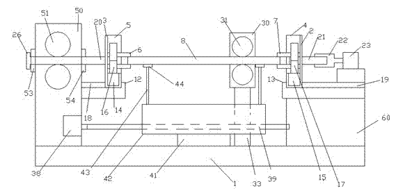
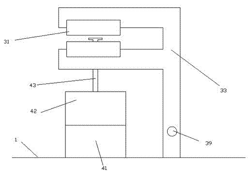
[0023] A sheet material processing method using a vacuum suction cup and a rolling device to move a lead screw left and right, which uses a sheet material processing device, and the sheet material processing device includes a bottom frame 1, a left frame 50 and a right frame 60, wherein the left The frame 50 is arranged on the left end of the underframe 1, the right frame 60 is arranged on the right end of the underframe 1, and a plate conveying device and a rolling device 30 are arranged between the left end and the right end of the underframe 1, wherein the plate conveying device can so that the carried plate moves along the front-to-back direction on the underframe 1, and the rolling device 30 can slide along the left-right direction on the underframe 1, and the front-back direction is a direction perpendicular to the left-right direction in the horizontal plane; the plate The conveying dev...
PUM
 Abstract
Description
Claims
Application Information