Die-cutting device special for groove strips such as guide grooves in car door and die-cutting blade of device

A technology of grooved strips and punching knives, which is applied in the field of special punching devices for grooved strips, can solve the problems of difficulty in ensuring machining accuracy and low operating efficiency, and achieve the effect of high punching accuracy and improved operating efficiency

Active Publication Date: 2014-05-28
NINGBO MINTH AUTOMOTIVE PARTS RES&DEV CO LTD
View PDF6 Cites 4 Cited by
  • Summary
  • Abstract
  • Description
  • Claims
  • Application Information

AI Technical Summary

Problems solved by technology

Due to its installation requirements, the upper guide groove of the above-mentioned car door after punching processing has high tolerance requirements for size, shape, and position. The two punching methods in the prior art are difficult to guarantee the processing accuracy requirements, and the operation efficiency is low.

Method used


Image

  • Die-cutting device special for groove strips such as guide grooves in car door and die-cutting blade of device
  • Die-cutting device special for groove strips such as guide grooves in car door and die-cutting blade of device
  • Die-cutting device special for groove strips such as guide grooves in car door and die-cutting blade of device

Examples


Embodiment 1

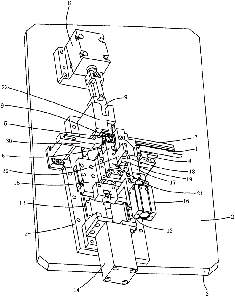
[0039] The special punching device for the groove bar of the present embodiment one is as follows: image 3 as shown, for figure 1 , figure 2 The end punching of the grooved strip workpiece 1 is shown. When punching, the grooved strip workpiece 1 is placed in a lateral vertical manner and then punched to its end; the punching device includes a base plate 2, and the shape of the contact surface that contacts the workpiece 1 is arranged on the base plate 2 to match the corresponding surface of the workpiece 1. Workpiece shelving block 4, workpiece inner stopper 5, and workpiece clamping mechanism for clamping the grooved bar workpiece 1 standing sideways. The workpiece clamping mechanism includes workpiece outer clamping block 6 and workpiece upper pressure block 7 driven by a power device The punching device also includes an end punching mechanism; the end punching mechanism includes a first oil cylinder 8 fixedly installed on the rear side of the bottom plate 2 in a horizon...

Embodiment 2

[0050] The special punching device for the groove bar in the second embodiment is a multi-directional combined punching device, such as Figure 11 as shown, for figure 1 , figure 2 The end punching of the grooved strip workpiece 1 is shown on the same machine as the lower side piece. When punching, the workpiece 1 of the grooved strip is placed in a lateral vertical manner; the punching device includes a base plate 2 and a shelf 3 fixedly placed above the base plate 2, and the shape of the contact surface and the groove in contact with the workpiece 1 are arranged on the base plate 2 The corresponding surface of the strip workpiece 1 matches, and is used to clamp the workpiece resting block 4, the workpiece inner stopper 5, and the workpiece clamping mechanism of the grooved strip workpiece 1 erected sideways. Block 6 and pressing block 7 above the workpiece; the punching device also includes an end punching mechanism and a lower side piece punching mechanism. The end punc...

Embodiment 3

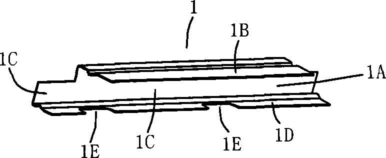
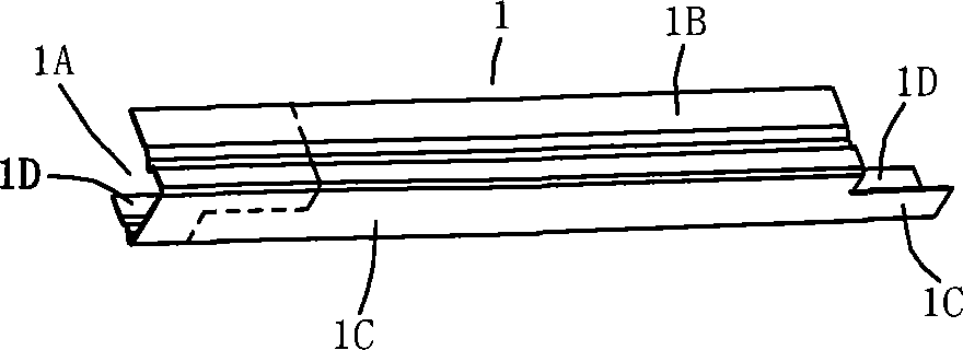
[0055] Such as Figure 12 Shown is an upper guide groove of an automobile door, which is also a groove bar with a concave cross section. The upper guide groove of a car door is generally formed by a continuous rolling process of metal strips, and is formed by an upper side piece 1B, a groove bottom 1C, a lower The groove 1A surrounded by the side piece 1D is cut off online; often for its installation needs, the end and side piece of the cut-off door upper guide groove need to be punched; the end is punched into the upper side piece 1B , the ends of the groove bottom 1C and the lower side panels 1D of different lengths are cut off, and the side panels are punched into notches or punched holes; before punching, the ends are as figure 2 The left end of the dotted line takes the left part as the part to be cut off. After punching, such as Figure 12 As shown, the part to be cut off at the end includes the end of the upper side piece 1B, the end of the groove bottom 1C, and the e...


PUM

PropertyMeasurementUnit
angleaaaaaaaaaa

Abstract

Disclosed is a die-cutting device for groove strips. A workpiece holding block (4), an inner workpiece stopper (5) and a workpiece clamping mechanism which are used for clamping a sideways upright groove strip workpiece (1) is arranged on the upper side of a bottom plate (2), and the workpiece clamping mechanism comprises an outer workpiece clamping block (6) and a top workpiece pressing block (7). An end die-cutting mechanism comprises a first oil cylinder (8) fixed on the rear side of the bottom plate (2), and a die-cutting blade (9) driven by the first oil cylinder (8) to perform die cutting from back to front. The shape and the size of the end portion of the outer workpiece clamping block (6) as well as the shape and the size of a notch of the die-cutting blade (9) are equal to those of a portion, needed to be reserved, of the die-cut end portion of the groove strip workpiece (1). The die-cutting blade (9) is a geometric body with the section in the shape of an angle rule. The shape and the size of an angle-rule-shaped notch (G) of the die-cutting blade (9) are also equal to those of the portion, needed to be reserved, of the die-cut end portion of the groove strip workpiece (1). The invention further provides a die-cutting device which is used for performing die-cutting on the end portions and lateral pieces of the groove strips at the same time, and particularly suitable for die-cutting of guide grooves in a car door.

Description

technical field [0001] The invention relates to a special punching device for groove strips such as the upper guide groove of a car door, which is used for punching grooved workpieces with a concave cross section similar to the upper guide groove of a car door, especially the end punching device. The utility model also relates to a punching knife suitable for punching the ends of groove bars such as upper guide grooves of car doors. Background technique [0002] In engineering, it is often necessary to perform multi-directional punching operations on some grooved workpieces with concave cross-sections, such as the upper guide groove of the car door, such as figure 1 , figure 2 As shown, metal strips are generally formed by continuous rolling process to form a groove 1A surrounded by upper side piece 1B, groove bottom 1C, and lower side piece 1D, and cut online; often for its installation needs, cut off The upper guide groove of the car door needs to be punched at the end ...

Claims


Application Information

Patent Timeline
Patent Type & Authority Applications(China)
IPC IPC(8): B21D28/02B21D28/14
Inventor 王小峰刘江
Owner NINGBO MINTH AUTOMOTIVE PARTS RES&DEV CO LTD
Why Eureka
Try Eureka