A punching equipment

A kind of equipment and punching technology, applied in metal processing equipment, forming tools, storage devices, etc., can solve the problems of incomplete processing, complicated product clamping, etc., and achieve the effect of high work efficiency, high punching precision and exquisite structure.

Active Publication Date: 2018-05-25
渭南木王智能科技股份有限公司
View PDF5 Cites 0 Cited by
  • Summary
  • Abstract
  • Description
  • Claims
  • Application Information

AI Technical Summary

Problems solved by technology

[0004] The purpose of the present invention is to provide a slotting equipment, which solves the problems of cumbersome product clamping and incomplete processing when the socket products are processed by a face milling cutter.

Method used


Image

  • A punching equipment
  • A punching equipment
  • A punching equipment

Examples


Embodiment Construction

[0027] The technical solutions of the present invention will be further described in detail below in conjunction with the description of the drawings and specific embodiments.

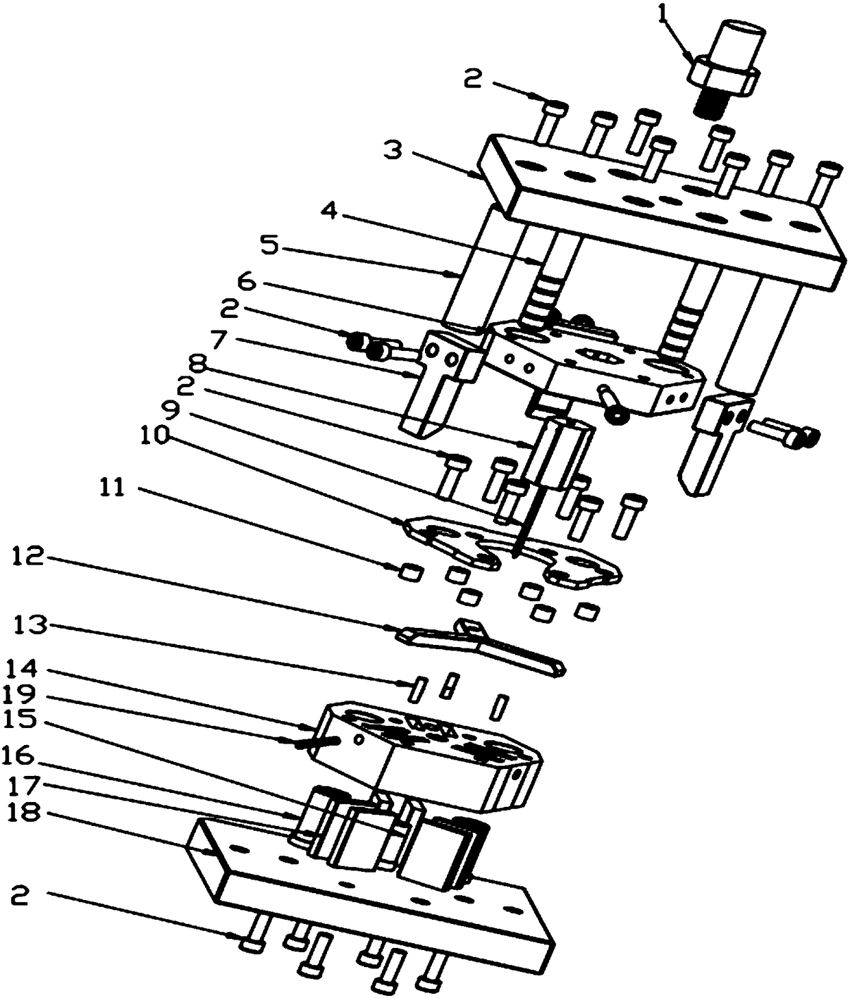
[0028] refer to figure 1 , a structural schematic diagram of a punching equipment of the present invention, including an upper template 3 and a lower template 18, the upper part of the upper template 3 is threadedly connected with a die handle 1, the die handle 1 is connected with other auxiliary punching equipment, and the upper template 3 is located at the lower Just above the template 18, the bottom side of the upper template 3 is fixed with the upper die holder 6 by the screw 2, the upper die holder 6 is equipped with a knife holder 8, and the cutter holder 8 is equipped with a cutter 9 for punching grooves.

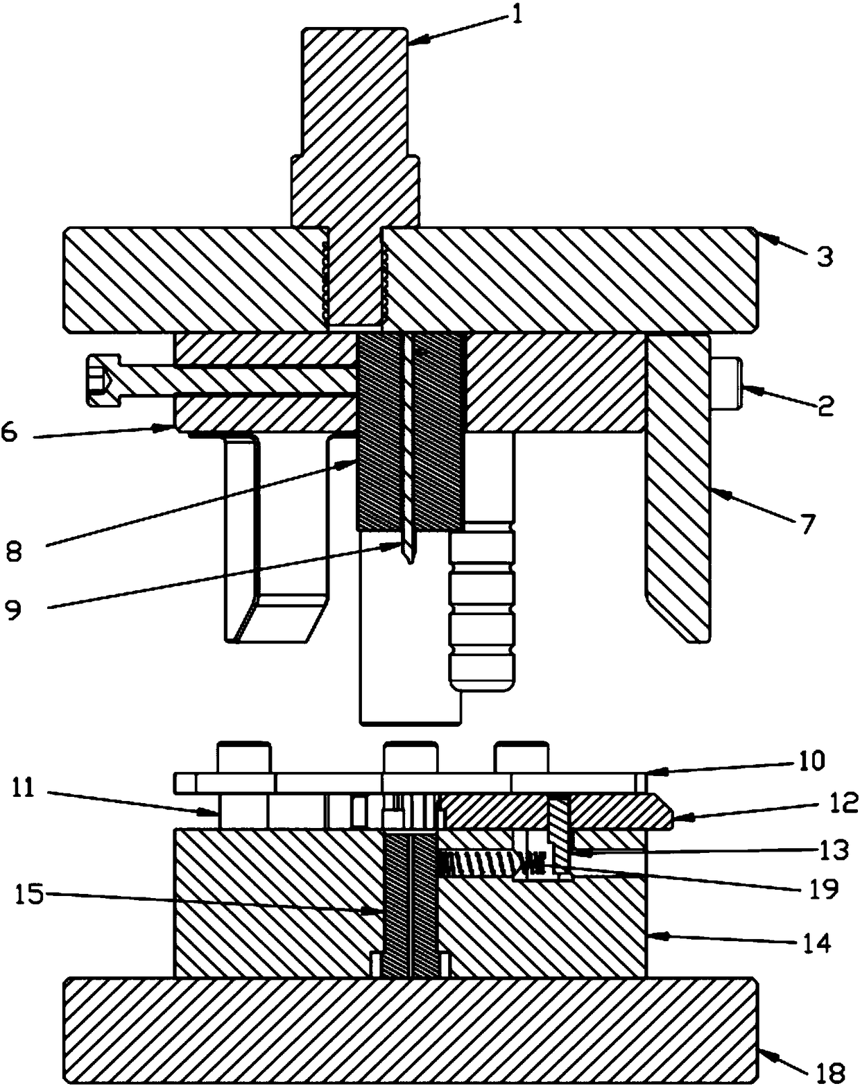
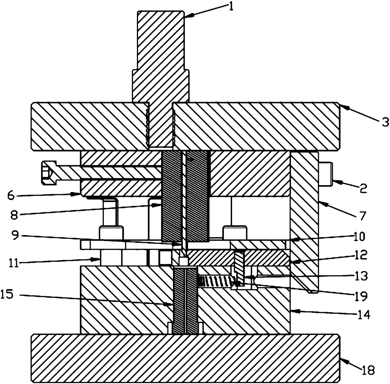
[0029] combine figure 2 and image 3 , the lower mold base 14 is fixed on the lower template 18 by screws 2, the lower mold base 14 is equipped with a fixed mold 15, the fixed mold 15 is l...


PUM


Abstract

The invention discloses notching equipment which comprises an upper mold plate (3) and a lower mold plate (18). The upper mold plate (3) is located over the lower mold plate (18). An upper mold base (6) is arranged on the lower surface of the upper mold plate (3). A tool apron (8) is assembled in the upper mold base (6). A tool (9) is assembled in the tool apron (8). A lower mold base (14) is arranged on the lower mold plate (18). A fixed mold (15) is assembled in the lower mold base (14). The fixed mold (15) is located under the tool apron (8). A through hole is formed in the fixed mold (15). A cover plate (10) is arranged on the lower mold base (14). A clamping device is assembled between the cover plate (10) and the lower mold base (14). The clamping center of the clamping device is located over the fixed mold (15). According to the technical scheme, the notching equipment has the advantages of being ingenious in structure, easy to operate, high in working efficiency, high in notching precision and the like.

Description

technical field [0001] The invention belongs to the field of mechanical processing equipment, and in particular relates to a special processing equipment for punching part grooves. Background technique [0002] In the prior art, face milling cutters are used to process slots or cross slots, but face milling cutters cannot process three slots in place at present, and cannot guarantee that there will be no slope at the root of the slot. [0003] Furthermore, in the process of machining the grooves on socket products with a face milling cutter, the product clamping is cumbersome, because there is no through groove in the radial direction, the processing of the face milling cutter is limited, and the root of the groove cannot be guaranteed, and the product drawing cannot be reached. requirements. Contents of the invention [0004] The object of the present invention is to provide a groove punching device, which solves the problems of cumbersome product clamping and incomplete...

Claims


Application Information

Patent Timeline
Patent Type & Authority Patents(China)
IPC IPC(8): B21D17/00B21D37/10B21D43/00
CPCB21D17/00B21D37/10B21D43/003
Inventor 马福斌付盼红
Owner 渭南木王智能科技股份有限公司
Why Eureka
Try Eureka