Collision resistant quad-rotor spherical unmanned aerial vehicle system

A drone and quadrotor technology, applied in the field of drones, can solve the problems that drones cannot enter the scene, are vulnerable to impact, crashes, etc., to reduce the possibility of damage and fall, improve collision resistance, reduce Effects of impact or disturbance of flight attitude

Active Publication Date: 2017-11-17
CHENGDU GUORONG TECH
View PDF6 Cites 19 Cited by
  • Summary
  • Abstract
  • Description
  • Claims
  • Application Information

AI Technical Summary

Problems solved by technology

[0005] (1) Carry a visible light + infrared camera to conduct reconnaissance and surveillance of the fire scene, but can only shoot in the building and cannot enter the interior;
[0006] (2) Carry gas detectors, toxic gas detectors, temperature sensors, etc. to detect the sky over open areas and the periphery of fire areas, and cannot enter the interior
[0008] However, for this new type of equipment, the fire brigade also has some limit

Method used


Image

  • Collision resistant quad-rotor spherical unmanned aerial vehicle system
  • Collision resistant quad-rotor spherical unmanned aerial vehicle system
  • Collision resistant quad-rotor spherical unmanned aerial vehicle system

Examples


Embodiment 1

[0056] A collision-resistant quadrotor spherical UAV system, such as Figure 10 As shown, it includes the flight platform 001 for performing flight missions, the mission payload 002 mounted on the flight platform 001 for detection, and the ground equipment for remote control, telemetry, and data transmission of the flight platform 001 or mission payload 002.

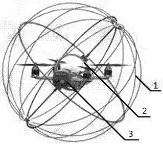
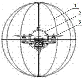
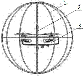
[0057] Such as Figure 1-Figure 5 As shown, the flight platform 001 includes a spherical frame mechanism 1, an aircraft body 3 completely located inside the spherical frame mechanism 1, and a support mechanism 2 that connects the spherical frame mechanism 1 and the aircraft body 3 as a whole.

[0058] The spherical frame mechanism 1 is in the structure of a globe latitude and longitude frame as a whole. The support mechanism 2 includes an annular connector located at the center of the spherical frame mechanism 1 and two support tubes 204 respectively arranged along the rotation axis of the globe. The center of gravity ...

Embodiment 2

[0063] This embodiment further optimizes the structure of the flying platform 001 on the basis of Embodiment 1, as Figure 1-Figure 4 As shown, the flight platform 001 is mainly composed of a spherical frame mechanism 1, an aircraft body 3 and a support mechanism 2 that connects the spherical frame mechanism 1 and the aircraft body. The spherical frame mechanism 1 and the support mechanism 2 together form a spherical protective structure that protects the aircraft body 3, improves the collision resistance of the entire flight platform 001, and effectively protects the aircraft body 3 from flying safely in complex environments. The task load 002 is integrated on the aircraft body 3 for easy disassembly and maintenance.

[0064] In this embodiment, the specific structures of the spherical frame mechanism 1 and the support mechanism 2 will be explained emphatically, and the principle of the spherical protection mechanism making the aircraft body 3 resistant to collisions will be ...

Embodiment 3

[0083] In this embodiment, on the basis of Embodiment 2, the material of the spherical frame mechanism 1 is further optimized. Such as Figure 5 As shown, the latitude annular frame 101 is a complete annular carbon fiber sheet; the longitude annular frame 102 is composed of four fan ring carbon fiber sheets; the longitude tube 103 is a glass fiber stringer; the bearing housing 104, The bearings 105 are all lightweight plastics; the end faces of the bearing seat 104 are respectively fixed with the glass fiber stringers passing through the annular carbon fiber sheet, and the fan ring carbon fiber sheet with one end fixed on the annular carbon fiber sheet. Each additional annular latitude ring is composed of four fan ring carbon fiber sheets spliced ​​together, or each additional annular latitude ring adopts a head-to-tail ring fiberglass stringer, or the additional annular latitude ring part adopts four fan ring carbon fiber It is composed of sheet splicing and partly adopts en...


PUM


Abstract

The invention discloses a collision resistant quad-rotor spherical unmanned aerial vehicle system comprising a flight platform, a mission load and ground equipment. The flight platform executes a flight mission, the mission load is carried on the flight platform for detecting, and the ground equipment conducts remote control, remote measuring and data transmission on the flight platform or the mission load. The flight platform comprises an integrally-arranged spherical frame mechanism, an internal aircraft body and a supporting mechanism. The spherical frame mechanism is overall of the structure of a longitude and latitude frame of a tellurion. The supporting mechanism comprises an annular connecting piece located at the center of the spherical frame mechanism, and two supporting pipes arranged along the rotation axis of the tellurion. The annular connecting piece and the spherical frame mechanism are connected to be a whole through the supporting pipes, and the gravity center of the flight platform mounted on the annular connecting piece is lower than that of the annular connecting piece. An integrally-arranged annular protective structure is provided for the aircraft body, so that the flight platform is good in collision resistance and still has high survival ability and adaptability in the complex environment.

Description

technical field [0001] The invention relates to the field of unmanned aerial vehicles, in particular to a collision-resistant four-rotor spherical unmanned aerial vehicle system. Background technique [0002] In recent years, my country's civil unmanned aerial vehicles have experienced a blowout development, and are widely used in entertainment, film and television, surveying and mapping, security and other fields. Due to the characteristics of flexible flight, relatively simple operation, and the ability to hover in situ, multi-rotor unmanned aerial vehicles are favored by firefighting forces, and have been increasingly used in fire fighting, emergency rescue scene investigation, monitoring, command and mapping Waiting for work. [0003] The use of drones in rescue by foreign fire departments has been very extensive. Fire departments in various countries are equipped with fire-fighting drones to perform reconnaissance, surveillance and other tasks. In March 2017, the New ...

Claims


Application Information

Patent Timeline
IPC IPC(8): B64C27/00B64C27/08B64C39/02
CPCB64C27/006B64C27/08B64C39/024B64U10/10B64U2201/10B64U2101/00B64U50/19B64U2201/20
Inventor 贺和平翟彬叶宇
Owner CHENGDU GUORONG TECH
Why Eureka
Try Eureka