Connecting structure for unmanned aerial vehicle body and wing

A technology for connecting structures and unmanned aerial vehicles, which is applied to the fuselage, aircraft parts, toy aircraft, etc., can solve the problems of difficult repair and replacement, low fatigue resistance, and complicated manufacturing process, and achieves strong replaceability and production. The effect of large batch size and simple manufacturing process

Inactive Publication Date: 2008-07-09
BEIHANG UNIV
View PDF0 Cites 23 Cited by
  • Summary
  • Abstract
  • Description
  • Claims
  • Application Information

AI Technical Summary

Problems solved by technology

[0003] Generally, the fuselage and wing of the UAV adopt a built-in connection. Once the connection is damaged, it is difficult to repair and replace, resulting in damage to the entire aircraft structure.
In the external connection method, the wing is often connected to the fuselage in a centralized connection method, and the joint uses the structural form of the fork joint, that is, the fork lug connection structure, which is composed of lugs and connecting bolts. It mainly transmits the load through the shearing of the bolts. , during the retransmission process, the shear force is directly transmitted by the lugs. When the load is too large, the damaged part is generally at the lugs. The structural stiffness in the direction, or increase the number of bolts, increase the shear surface, to improve the stiffness, so it is only suitable for wings with thinner airfoils, and the outline size of a single part of the structure is too large, and its shape is complicated. Parts require large machine tool equipment during processing, and the manufacturing process is complex, the processing deformation is large, and the structure will warp

Method used


Image

  • Connecting structure for unmanned aerial vehicle body and wing
  • Connecting structure for unmanned aerial vehicle body and wing
  • Connecting structure for unmanned aerial vehicle body and wing

Examples


Embodiment Construction

[0026] The present invention will be further described in detail below in conjunction with the accompanying drawings.

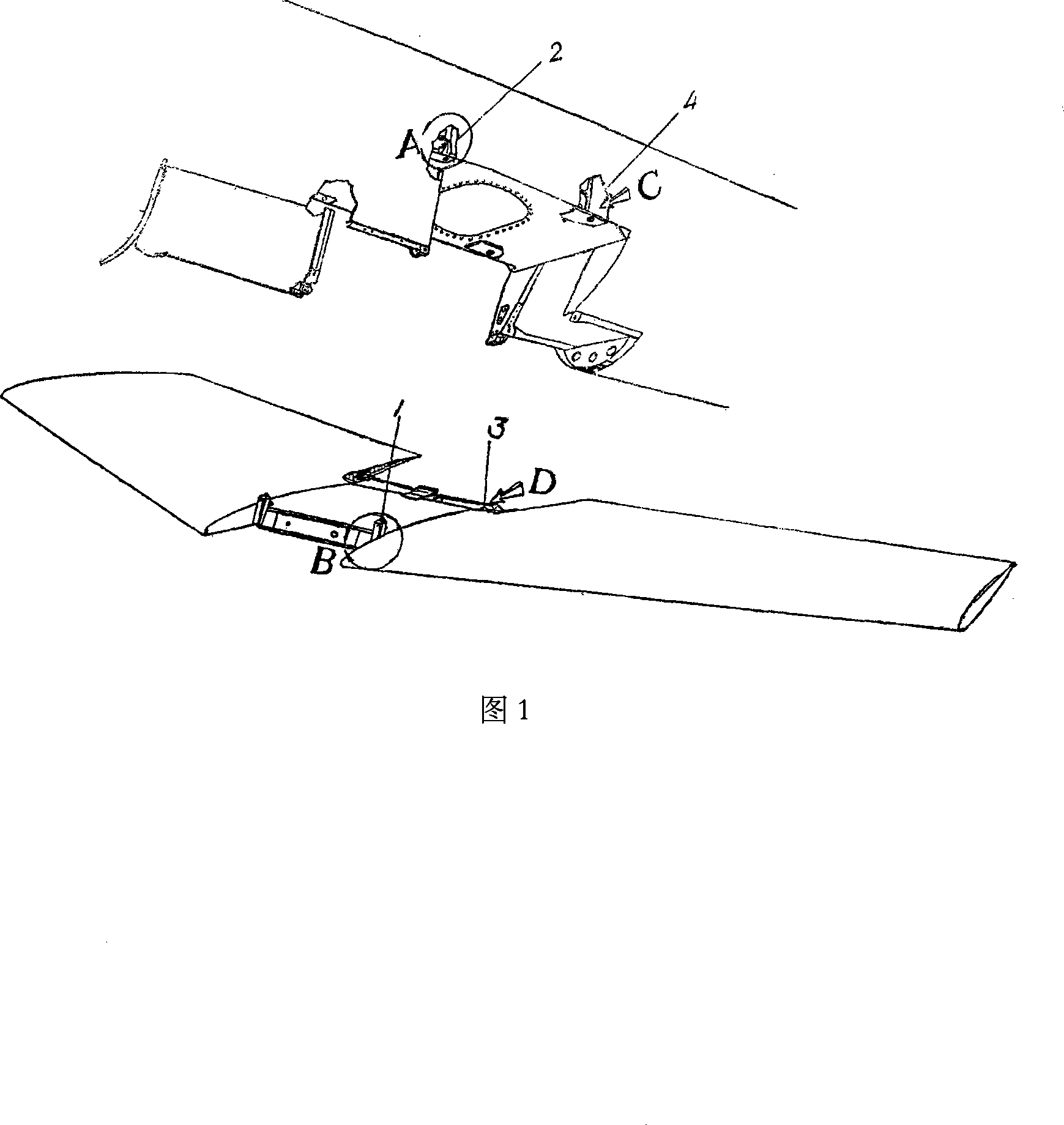
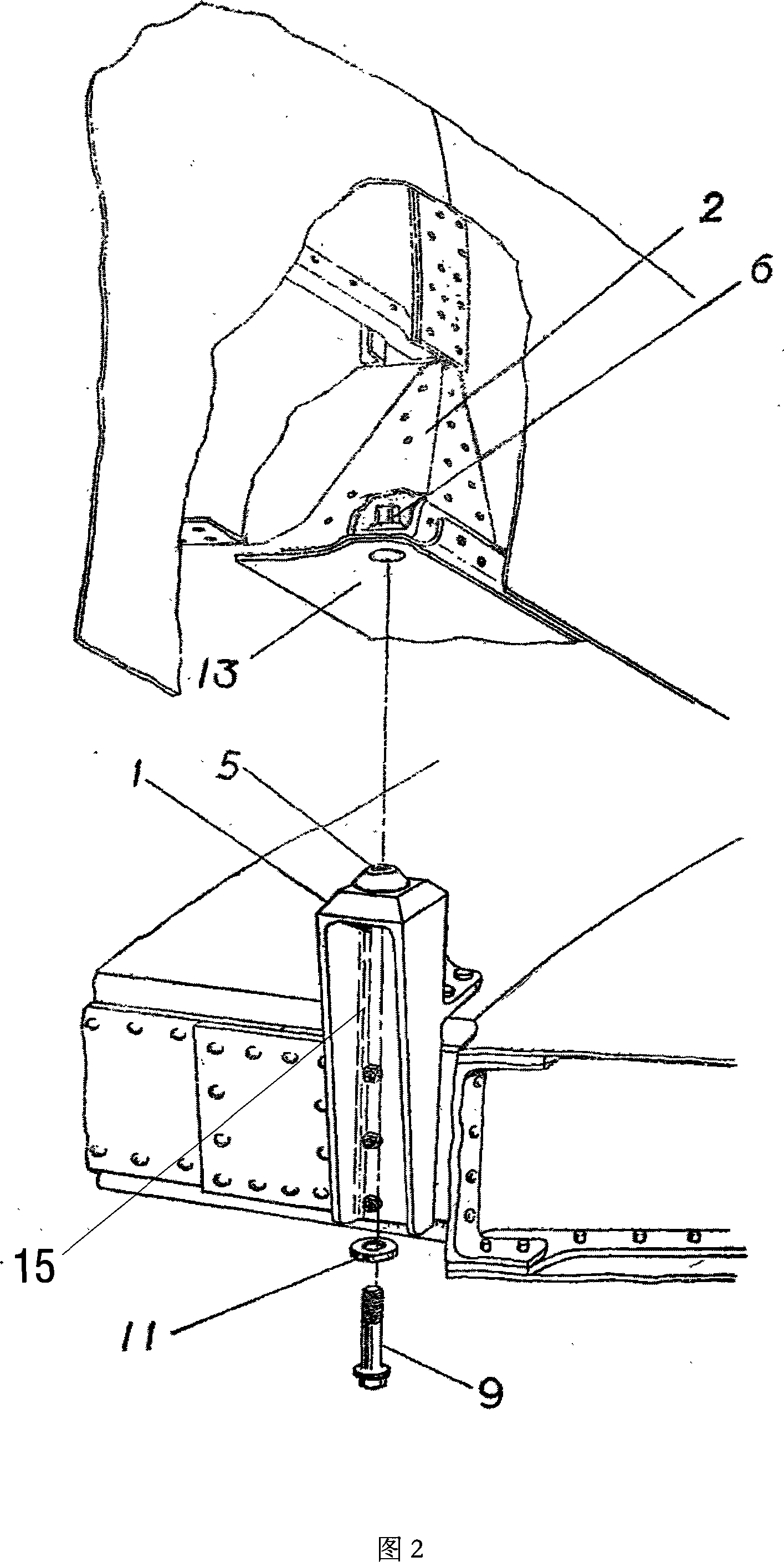
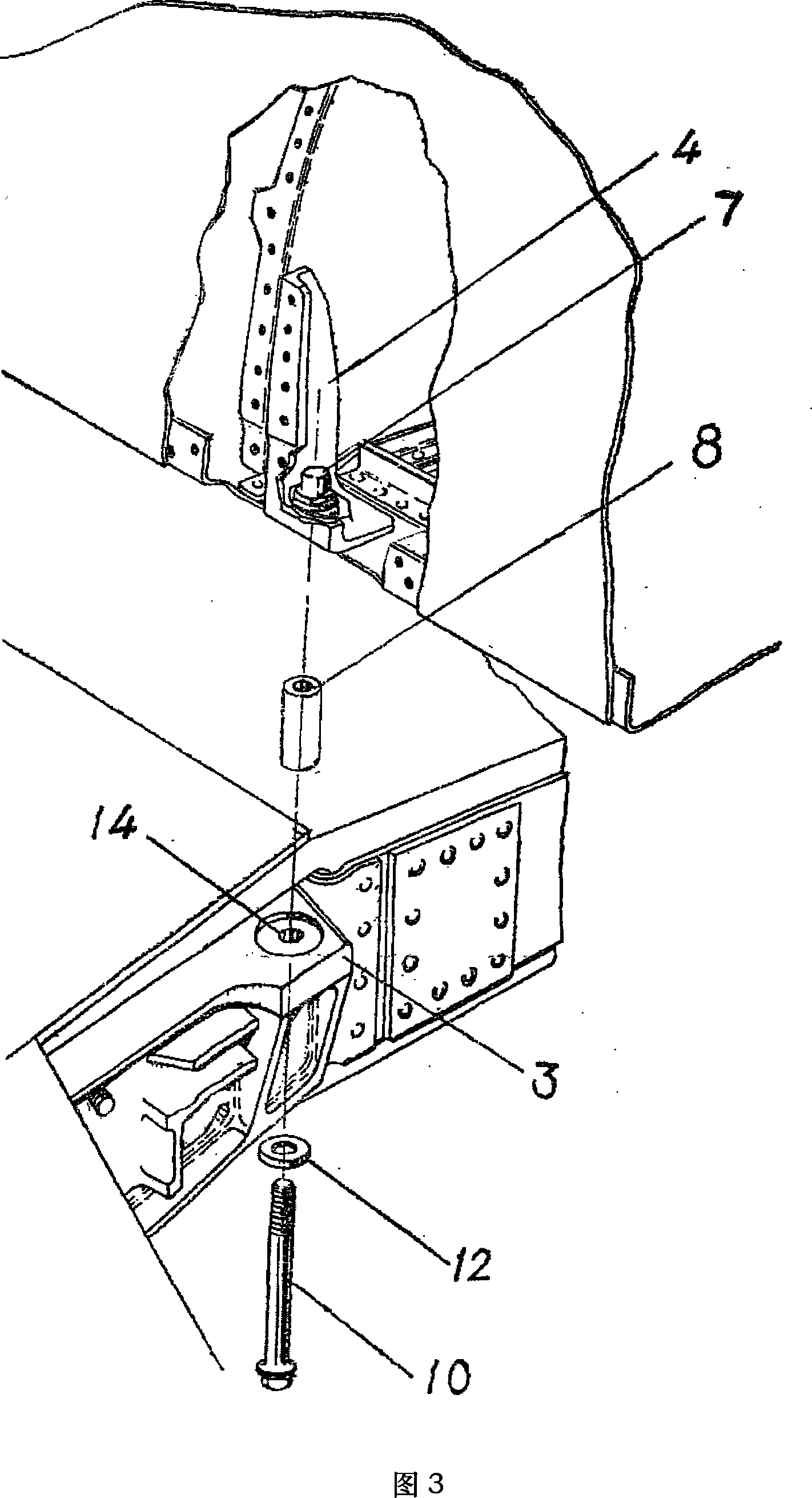
[0027] The connecting structure of a kind of unmanned aerial vehicle fuselage of the present invention and wing is realized by connecting a pair of front and rear joints on the wing and a pair of front and rear joints on the bottom plate of the fuselage fuel tank. The front joint 2 is connected, and the rear joint 3 of the wing is connected with the rear joint 4 of the fuselage. The enlarged view of the connection structure of parts A and B is shown in Figure 2, combined with the structural diagram of the front joint 1 of the wing in Figure 4 and the front of the fuselage in Figure 5 The structural diagram of the joint 2 shows that the front joint 1 of the wing is connected to the upper surface of the wing through the side ear 16, and the front part is riveted to the wing box wall plate through a number of screw holes in the washing tank 15, and its top is equ...


PUM


Abstract

The present invention discloses a connection structure of an airframe-airfoil of an unmanned aerial vehicle, which is realized by the connection of a pair of front and back joints of the airfoil and a pair of front and back joints at the oil box soleplate of the airframe that is the front joint of the airfoil is connected with the front joint of the airframe by bolts, and the back joint of the airfoil is connected with the back joint of the airframe by bolts. The airfoil and the airframe are linked just by four pairs of joints and four connection pieces, and the force transmission of the connection pieces is reasonable, which reduces the connection of joint parts and the concentration of stress; a majority of load is discharged during flying, which improves the anti-fatigue performance. The present invention has the characteristics of small size, good flexibility and large production batch. The structure can improve the rigidity of the joints to ensure the firm connection of the airframe and the airfoil and the high efficiency of the structure, and the structure belongs to the external connection, which has strong changeability and meets the requirement of combat readiness.

Description

technical field [0001] The invention belongs to the field of aviation machinery, and in particular relates to a connection structure between a fuselage and a wing of an unmanned aerial vehicle. Background technique [0002] At present, UAVs have been widely used in many fields such as campaign and strategic reconnaissance, surveillance, target positioning, target damage assessment, electronic countermeasures, and communication relay. Due to the advantages of UAVs such as low cost, good penetration capabilities and their outstanding performance in practice, the troops also urgently need to use various UAVs with excellent performance. Therefore, safety, reliability, economy and use requirements are the biggest challenges for UAV design. The connection between the fuselage and the wing bears a large load, which is a key fatigue component related to the flight safety of the aircraft. On the one hand, the loads it bears come from various mass forces (including the mass forces of...

Claims


Application Information

Patent Timeline
Patent Type & Authority Applications(China)
IPC IPC(8): B64C1/00A63H27/18
Inventor 李大伟范曼华李仪郭伟
Owner BEIHANG UNIV
Why Eureka
Try Eureka