Circuit breaker structure achieving rapid releasing through electric repulsion force and circuit breaker

A technology of electric repulsion and circuit breaker, which is applied in the direction of protection switch operation/release mechanism, etc., can solve the problems of complex transmission relationship time delay, unreachable action stability, increased manufacturing and assembly links, etc., to improve short-circuit breaking capacity and structure Simple, reduce the effect of allowing energy

Active Publication Date: 2014-07-16
浙江天正智能电器有限公司
View PDF5 Cites 4 Cited by
  • Summary
  • Abstract
  • Description
  • Claims
  • Application Information

AI Technical Summary

Problems solved by technology

However, this solution has many transmission links and unsatisfactory deficiencies in motion stability. Therefore, it has no advantages compared with the traditional method of actuating by responding to the action time and detecting the current signal, and the transmission chain, that is, the transmission relationship is complicated. It is also accompanied by a certain time delay and the use of transmission rods, which increases the number of manufacturing and assembly links and affects the efficiency of mass production
[0005] And the patent No. CN101170031.A discloses a kind of fast breaking low-voltage circuit breaker, the tripping process of this patent scheme is that the executive unit between the moving contact and the tripping rod transmits the repelling movement of the moving contact to the tripping The tripping rod, and then the tripping rod makes the operating mechanism trip, and drives the moving contact to trip to complete the breaking operation, and this scheme simply contacts the tripping rod and the moving contact through the active part and the passive part of the execution unit. , so that the moving contact drives the action of the executive unit to trip the trip lever. However, this scheme will cause the misoperation of the executive unit and the occurrence of misoperation due to the action of the moving contact when the opening and closing action is manually operated.

Method used


Image

  • Circuit breaker structure achieving rapid releasing through electric repulsion force and circuit breaker
  • Circuit breaker structure achieving rapid releasing through electric repulsion force and circuit breaker
  • Circuit breaker structure achieving rapid releasing through electric repulsion force and circuit breaker

Examples


Embodiment Construction

[0037] Embodiments of the present invention will be further described below in conjunction with accompanying drawings:

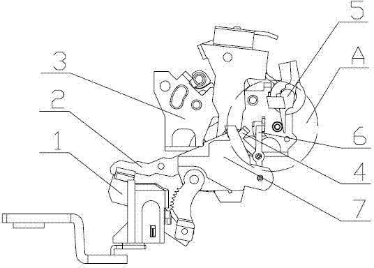
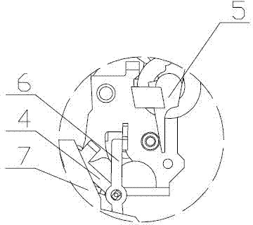
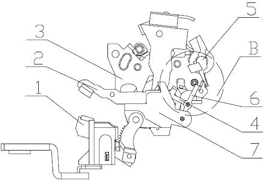
[0038] Such as figure 1 , figure 2 , Figure 7 with Figure 8 shown, which includes:

[0039] Static contact 1;

[0040] The moving contact 2 is fixed on the rotating shaft 7;

[0041] The elastic member installed in the rotating shaft 7 promotes the linkage between the moving contact 2 and the rotating shaft 7; the moving contact overcomes the elastic force of the elastic member and forms a relative motion cooperation with the rotating shaft 7;

[0042] The operating mechanism 3 is fixed on the rotating shaft 7 and cooperates with the rotating shaft 7 to perform the opening or closing action of the moving contact 2 and the static contact 1;

[0043] Between the moving contact 2 and the operating mechanism 3 is provided an execution unit for performing quick breaking tasks, the execution unit includes a drawbar 5, and the drawbar 5 is hingedly matched...


PUM


Abstract

The invention relates to a circuit breaker structure achieving rapid releasing through electric repulsion force and a circuit breaker. The circuit breaker structure comprises a static contact, a moving contact, an elastic piece and an operating mechanism. An execution unit is arranged between the moving contact and the operating mechanism and comprises a draw bar, the draw bar and the operating mechanism are hinged and matched, the draw bar moves to actuate the operating mechanism, a first connecting bar is arranged at the tail end of the moving contact, a second connecting bar is fixedly connected with the tail end of a rotating shaft, the other end of the second connecting bar actuates the draw bar, one end of the first connecting bar is rotationally connected with the tail end of the moving contact, and the other end of the first connecting bar is fixedly connected with the middle of the second connecting bar. When the rotating shaft and the moving contact are linked, the first connecting bar and the second connecting bar do not move. When the moving contact overcomes elastic force of the elastic piece and moves relative to the rotating shaft, the first connecting bar drives the second connecting bar to move to drive the draw bar to make the operating mechanism released, when the moving contact is repelled by the electric repulsion force, the circuit breaker operating mechanism can be synchronously triggered, the mechanism can be rapidly released, and secondary drop of the moving contact and fusion welding of the contacts can be avoided.

Description

technical field [0001] The invention belongs to the technical field of low-voltage circuit breakers, and in particular relates to a circuit breaker structure and a circuit breaker which use electric repulsion to perform linkage, quick release, and short-circuit protection. Background technique [0002] Low-voltage circuit breakers can be used for short-circuit current protection of lines. For some current-limiting circuit breakers, before the actual fault short-circuit current of the line reaches the peak value of the expected short-circuit current of the line, the moving contacts will be repulsed under the action of electric repulsion to generate an arc, thereby limiting the further increase of the short-circuit current . Then the electromagnetic protection mechanism of the circuit breaker will drive the operating mechanism to act, the circuit breaker will trip and open, the arc will be extinguished, and the short-circuit fault current will be cut off. [0003] However, t...

Claims


Application Information

Patent Timeline
Patent Type & Authority Applications(China)
IPC IPC(8): H01H71/43
Inventor 丁国辉
Owner 浙江天正智能电器有限公司
Why Eureka
Try Eureka