Leakage protecting apparatus

A leakage protection device and resistance technology, applied in the direction of circuit devices, emergency protection circuit devices, automatic disconnection emergency protection devices, etc., can solve the problems of electric shock casualties, failure to ensure electricity safety, failure to achieve protection, etc., to achieve good The effect of security protection

Active Publication Date: 2013-03-27
刘睿刚
View PDF2 Cites 0 Cited by
  • Summary
  • Abstract
  • Description
  • Claims
  • Application Information

AI Technical Summary

Problems solved by technology

It can be seen from this that the prerequisite for the existing leakage protection device to trip when the load terminal is faulty or the ground wire is accidentally electrified is that there must be a residual current between the load terminal phase and the neutral line or that there must be an accidental current flow on the load terminal ground wire. and the working power supply must be normal to trip, otherwise the protection cannot be realized
Therefore, the existing leakage protection device has the following defects: when in use, no matter when the ground wire of the grounding protection system is missing (for example: no grounding is caused by a virtual connection of the ground wire of the socket) and the insulation fault of the electrical appliance at the load end of the leakage protection device leaks, or When the grounding protection system is abnormal (for example: phase wire, grounding wire short circuit) and the grounding wire is accidentally electrified, it will cause the exposed metal parts of the electrical appliances to carry dangerous voltage, but they have not formed a loop, so there is no residual current or grounding. Therefore, although the exposed metal parts of electrical appliances have been charged with dangerous voltage, the existing leakage protection devices will not trip automatically in this case, only when the human body or livestock touch these charged parts When the exposed metal parts are exposed, the human body or livestock will form a circuit, resulting in residual current or ground wire accidental current, which will cause the leakage protection device to trip within 0.1S and disconnect the phase wire, neutral wire, and ground wire, although it can be released in time. The buckle protects the life safety of people or livestock, but in this case, the existing leakage protection device must first pass through the human body or livestock to generate residual current or ground wire accidental current and flow through the human body or livestock before it can trip. The phase wire, neutral wire, and ground wire are disconnected; at the same time, when the power supply is abnormal (for example: when the phase wire or neutral wire at the power supply end is accidentally disconnected, or the phase wire and the ground wire at the power end are reversed), the current leakage The electromagnetic trip and the electromagnetic coil of the lock device in the protection device cannot generate electromagnetic force because they are not energized, so the leakage protection device cannot trip, and the phase line contact, neutral line contact and ground line contact will still be kept in position. In the connected state, once the ground wire is accidentally electrified (for example: the phase wire and the ground wire are reversed) or the phase wire leaks, the leakage protection device cannot trip the phase wire contact, the neutral wire contact and the ground wire. contact break
[0003] The Chinese patent document publication number is CN102064522A also discloses a novel leakage protector, which is provided with a phase wire, a neutral wire, a ground wire, a tripping coil, a zero-sequence current transformer and a control circuit. It includes a main control chip, a silicon controlled rectifier and a rectifier. Although this kind of leakage protector is connected with the primary winding of a zero-sequence current transformer between the ground wire and the neutral wire, the zero-sequence current transformer in the leakage protector is secondary One output end of the primary winding is grounded, and the other output end of the secondary winding of the zero-sequence current transformer is connected to an input end (pin ③) of the main control chip in the control circuit, so that both ends of the output end of the zero-sequence current transformer secondary winding There is no loop formed between the input ends of the main control chip in the control circuit, so the main control chip cannot amplify the signal output by the secondary winding of the zero-sequence current transformer, and the main control chip cannot output signals to trigger the thyristor The leakage protector trips and cuts off the power supply, so the purpose of ensuring the safety of electricity use cannot be achieved; and one end of its tripping coil is connected to the phase line, and one input end of the rectifier and the other input end are respectively connected to the other end of the tripping coil and zero. Line connection, that is, the tripping coil is connected between the phase line and the neutral line through the rectifier and the thyristor to form a series circuit. By triggering the conduction of the thyristor, the tripping coil is energized to generate electromagnetic attraction to trip the leakage protector. Power off, so that when the power supply is abnormal (for example, the zero line of the power supply is accidentally disconnected) and the electrical appliance leaks, because its control circuit and tripping coil cannot work, the electromagnetic coil does not generate electromagnetic attraction, so the leakage protector cannot trip. Power outages cannot guarantee the safety of people using electricity
[0004] To sum up, the existing leakage protection device still causes electric shock casualty accidents

Method used


Image

  • Leakage protecting apparatus
  • Leakage protecting apparatus
  • Leakage protecting apparatus

Examples


Embodiment 1

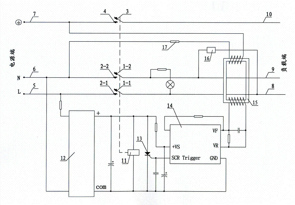
[0028] see figure 1 As shown, a leakage protection device is mainly composed of a shell, a phase wire 5 at the power supply end, a neutral wire 6, a ground wire 7, a load end phase wire 8, a neutral wire 9, a ground wire 10, a rectifier circuit 12, a thyristor 13, an amplifying Circuit 14, zero-sequence current transformer 15, test circuit 16, current-limiting resistance-capacitance element 17, electromagnetic tripping and locking device. The electromagnetic tripping and locking device is mainly composed of electromagnetic coil 11 and its drive circuit, phase line contacts 1-1 and 2-1, neutral line contacts 1-2 and 2-2, ground line contacts 3 and 4, springs , Reset button composition.

[0029] In this embodiment, the driving circuit of the electromagnetic coil 11 is composed of a rectifier circuit 12, a thyristor 13, and an amplifying circuit 14. One output end and the other output end of the secondary winding of the zero-sequence current transformer 15 are connected with the...

Embodiment 2

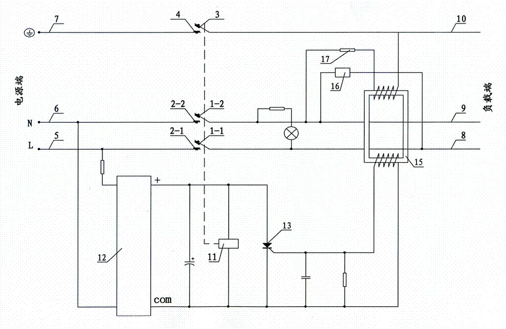
[0038] see figure 2 As shown, compared with Embodiment 1, this embodiment cancels the amplification circuit 14 described in Embodiment 1 in the driving circuit of the electromagnetic coil. In this embodiment, the driving circuit of the electromagnetic coil 11 is composed of a rectifier circuit 12 and a thyristor 13. One output terminal and the other output terminal of the secondary winding of the zero-sequence current transformer 15 are respectively connected to the trigger pole of the thyristor 13. Connected to the cathode, the anode and cathode of the thyristor 13 are respectively connected to the positive pole (+) of the output terminal of the rectifier circuit 12 and the common pole (com), and the one end and the other end of the electromagnetic coil 11 are respectively connected to the anode and the cathode of the thyristor 13 , the detection winding of the zero-sequence current transformer 15 is connected in series with the current-limiting resistance-capacitance elemen...

Embodiment 3

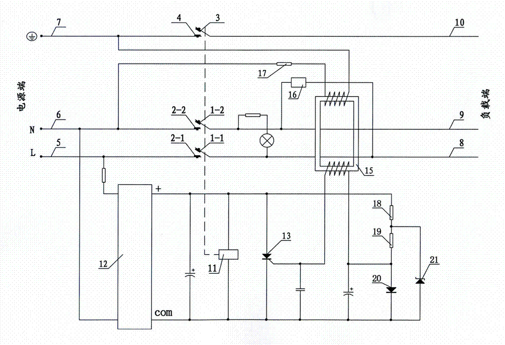
[0043] see image 3As shown, compared with Embodiment 2, this embodiment increases the clamping diode 20 anode clamp composed of the first resistor 18, the second resistor 19, the clamping diode 20, and the Zener diode 21 in the driving circuit of the electromagnetic coil. bit circuit, a loop formed by connecting the first resistor 18, the second resistor 19, and the clamping diode 20 in series is connected between the positive pole (+) and the common pole (com) of the output terminal of the rectifier circuit 12, and one end of the first resistor 18 is connected to The positive pole (+) of the output terminal of the rectifier circuit 12 is connected, the other end of the first resistor 18 is connected to one end of the second resistor 19, the other end of the second resistor 19 is connected to the positive pole of the clamp diode 20, and the negative pole of the clamp diode 20 is connected to the output terminal of the rectifier circuit 12 The other end of the first resistor 1...


PUM


Abstract

The invention discloses a leakage protecting apparatus, which not only can prevent electric-shock accidents caused by malfunctions of electric appliances, but also can prevent the electric-shock accidents caused by accidental electrification of a ground wire. A zero-sequence current mutual inductor of the leakage protecting device is also provided with a detection winding, the detection winding of the zero-sequence current mutual inductor is separated from a secondary winding of the zero-sequence current mutual inductor in an insulation way, a detection circuit which is formed by serially joining the detection winding of the zero-sequence current mutual inductor and a current-limiting resistance-capacitance element is arranged between a ground wire and a zero wire, one terminal and another terminal of an electromagnetic coil are respectively connected with the anode and the cathode of a controllable silicon, and one output end and another output end of a primary winding of the zero-sequence current mutual inductor are respectively connected with one input end and another input end of a driving circuit of the electromagnetic coil.

Description

technical field [0001] The invention relates to the technical field of electricity safety protection, in particular to an electric leakage protection device. Background technique [0002] The Chinese patent literature publication number is CN1142618C discloses a kind of earth leakage protection device which can be opened and closed. The earth leakage protection device is not only equipped with a zero-sequence current transformer through which both the phase line and the neutral line pass, but also has a ground wire through It is an electrified detection sensor for the over ground wire, so it can not only detect whether there is any residual current between the phase wire and the neutral wire at the load end, when the residual current between the phase and neutral wires reaches the preset threshold (for example: 10mA ), it will trip immediately and cut off the phase wire, neutral wire and ground wire; and when the ground wire is accidentally electrified due to an abnormal gro...

Claims


Application Information

Patent Timeline
Patent Type & Authority Patents(China)
IPC IPC(8): H02H3/32
Inventor 刘睿刚
Owner 刘睿刚
Why Eureka
Try Eureka