Method and apparatus for minimally invasive insertion of intervertebral implants

a technology of intervertebral implants and implants, which is applied in the field of medical devices, can solve the problems of high cost, long hospital stay, and inability to meet the needs of patients, and achieve the effect of facilitating the introduction of instruments and/or devices

Active Publication Date: 2013-03-12
DEPUY SYNTHES PROD INC
View PDF100 Cites 224 Cited by
  • Summary
  • Abstract
  • Description
  • Claims
  • Application Information

AI Technical Summary

Benefits of technology

[0011]In one embodiment, the implant is advantageously introduced via a minimally invasive procedure, taking a posterolateral approach at least partially through Kambin's triangle in a manner that advantageously provides protection to the exiting and traversing nerves. In one arrangement, to facilitate introduction of instruments and / or devices at least partially through Kambin's triangle a foraminoplasty is formed. In one embodiment, the foraminoplasty is performed using one or more features provided one or more dilation tubes that can be used to dilate tissue.

Problems solved by technology

Additionally, the vertebrae and associated connective elements are subject to injuries, including fractures and torn ligaments and surgical manipulations, including laminectomies.
Notwithstanding the variety of efforts in the prior art described above, these intervertebral implants and techniques are associated with another disadvantage.
In particular, these techniques typically involve an open surgical procedure, which results in higher cost, lengthy in-patient hospital stays and the pain associated with open procedures.
This results in additional movement of the patient.

Method used


Image

  • Method and apparatus for minimally invasive insertion of intervertebral implants
  • Method and apparatus for minimally invasive insertion of intervertebral implants
  • Method and apparatus for minimally invasive insertion of intervertebral implants

Examples


Embodiment Construction

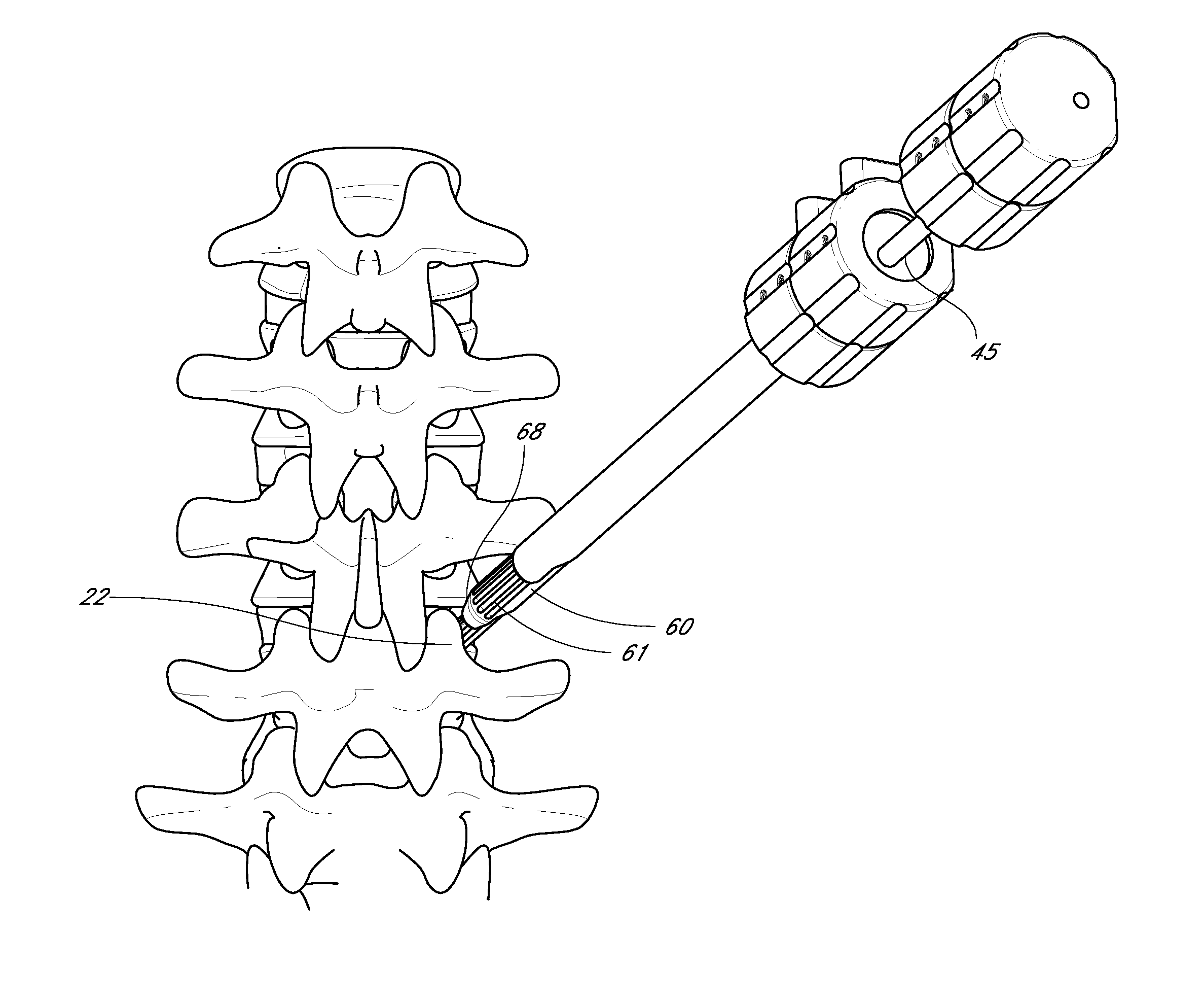
[0085]In accordance with certain embodiments disclosed herein, an improved apparatus for inserting an intervertebral implant is provided. For example, in one embodiment, the apparatus may be used to insert surgical instruments and / or one or more intervertebral implants through a minimally invasive procedure to reduce trauma to the patient and thereby enhance recovery and improve overall results. By minimally invasive, Applicant means a procedure performed percutaneously through an access device in contrast to a typically more invasive open surgical procedure.

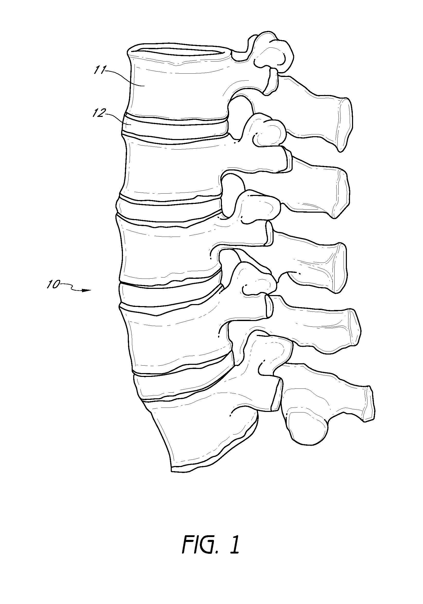
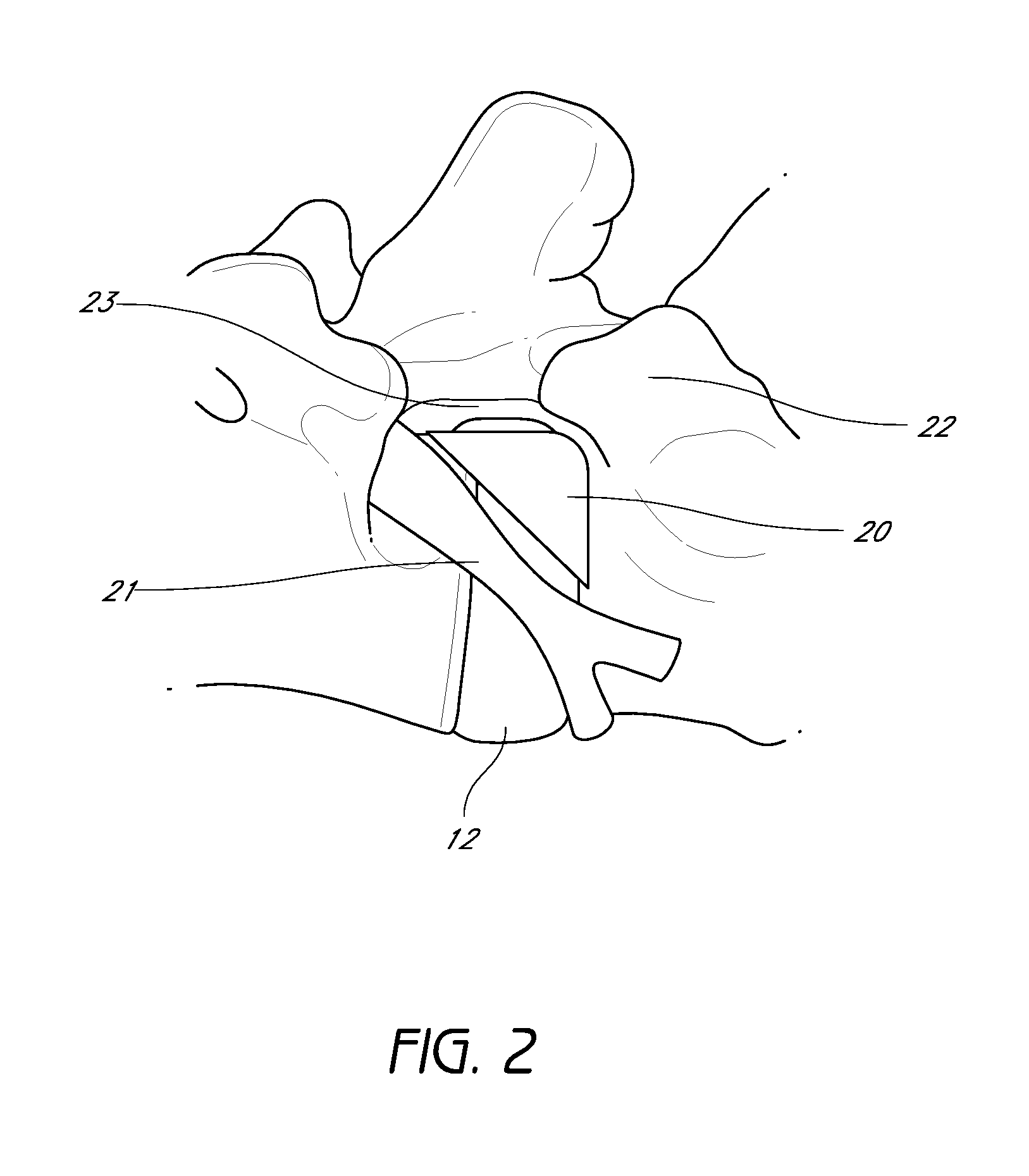
[0086]Certain embodiments disclosed herein are discussed in the context of an intervertebral implant and spinal fusion because of the device and methods have applicability and usefulness in such a field. The device can be used for fusion, for example, by inserting an intervertebral implant to properly space adjacent vertebrae in situations where a disc has ruptured or otherwise been damaged. “Adjacent” vertebrae can include thos...


PUM


Abstract

A dilation introducer for orthopedic surgery is provided for minimally invasive access for insertion of an intervertebral implant. The dilation introducer may be used to provide an access position through Kambin's triangle from a posterolateral approach. A first dilator tube with a first longitudinal axis is provided. A second dilator tube may be introduced over the first, advanced along a second longitudinal axis parallel to but offset from the first. A third dilator tube may be introduced over the second, advanced along a third longitudinal axis parallel to but offset from both the first and the second. An access cannula may be introduced over the third dilator tube. With the first, second, and third dilator tubes removed, surgical instruments may pass through the access cannula to operate on an intervertebral disc and / or insert an intervertebral implant.

Description

CROSS-REFERENCE TO RELATED APPLICATIONS[0001]This application claims a priority benefit to U.S. Provisional Application No. 61 / 530,031, filed Sep. 1, 2011, to U.S. Provisional Application No. 61 / 504,120, filed Jul. 1, 2011, to U.S. Provisional Application No. 61 / 471,030, filed Apr. 1, 2011 and to U.S. Provisional Application No. 61 / 451,379, filed Mar. 10, 2011, the entire disclosures of these prior applications are hereby incorporated by reference in their entireties and should be considered a part of this specification.BACKGROUND OF THE INVENTION[0002]1. Field of the Invention[0003]The present application relates to medical devices and, more particularly, to a medical device and method for the treating the spine.[0004]2. Description of the Related Art[0005]The human spine is a flexible weight bearing column formed from a plurality of bones called vertebrae. There are thirty-three vertebrae, which can be grouped into one of five regions (cervical, thoracic, lumbar, sacral, and coccy...

Claims


Application Information

Patent Timeline
Patent Type & Authority Patents(United States)
IPC IPC(8): A61B17/88
CPCA61B17/1757A61M29/00A61B17/8858A61F2/447A61F2/4611A61B17/3417A61B17/3421A61B17/3468A61B2017/00261A61F2002/30281A61F2002/30387A61F2002/3039A61F2002/30397A61F2002/304A61F2002/30434A61F2002/30507A61F2002/30522A61F2002/30538A61F2002/30551A61F2002/30556A61F2002/30579A61F2002/30601A61F2002/30827A61F2002/30841A61F2002/30878A61F2002/30904A61F2002/4623A61F2002/4624A61F2002/4627A61B2017/3447A61B2017/3449A61F2002/30433A61F2002/3055A61F2/4603
Inventor MORGENSTERN LOPEZ, RUDOLFFLOWER, ROBERTWARREN, CHRISTOPHER
Owner DEPUY SYNTHES PROD INC
Why Eureka
Try Eureka